16
2
gg
Q
R
S
hh
gg
hh
ee
dd
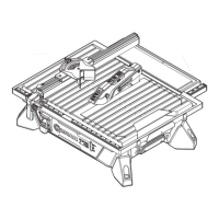
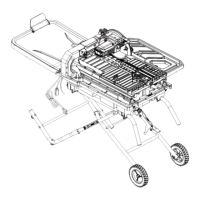
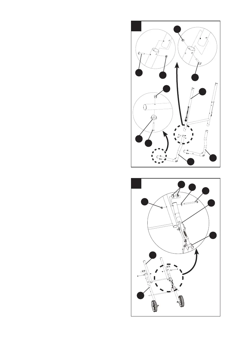
Assembling the left and right outer tubes
(Fig. 2) - BAG U
● Attach the left lower outer tube (R) to one
side of the upper outer tube assembly (Q)
using two screws (gg) and two lock nuts (hh),
as shown.
●
Tighten using the
adjustable
wrench (not
included) for the nuts (hh) and the Phillips
screwdriver (not included) for the screws (gg).
● Repeat the above steps to assemble the
right lower outer tube
.
Assembling the foot pads (Fig. 2) - BAG U
● Attach one foot pad (ee) to the left lower
outer tube (R) using one hex bolt (dd) and
one crown nut (), as shown.
● Tighten using the adjustable wrench (not
included) for the crown nut () and the 10 mm
wrench (not included) for the hex bolt (dd).
● Repeat the above steps to assemble the
other three foot pads
.
Assembling the center brace to the inner leg
assembly (Fig. 3) - BAG U
● Place the center brace (M) on top of the inner
leg assembly (N) (curve side up) with the
stop pin (1) under the foot release lever (BB).
NOTE: The stop pins rest on top of the inner
leg assembly.
● Attach the center brace (M) to the inner leg
assembly (N) using two hex bolts (aa), two
spring washers (jj), four small spacers (bb)
and two nuts (cc), as shown.
NOTE: The at sides of two spacers should
be placed against each other.
● Tighten with the adjustable wrench (not
included) for the nuts (cc) and the 13 mm
wrench (not included) for the hex bolts (aa).
NOTE: Do not overtighten, because doing so
will not allow the leg assembly to move.
3
aa
cc
M
1
BB
N
bb
jj
 Loading...