33
33
PP
4
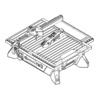
BOTTOM VIEW
34
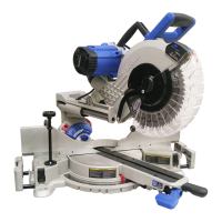
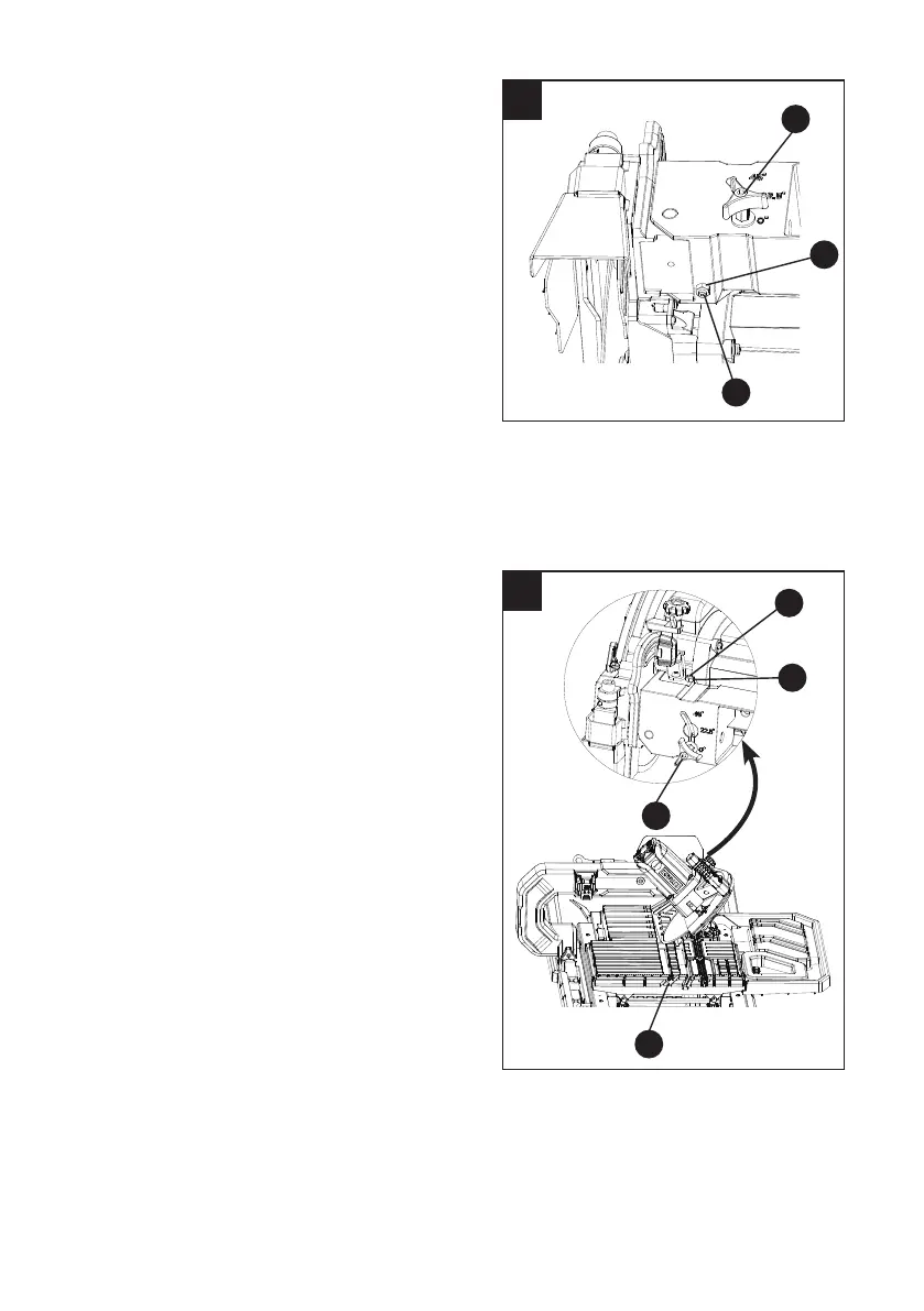
Adjusting the cutting wheel 90° to sliding
table (Fig. 32, 33)
● Disconnect the saw from the power source.
● Loosen the bevel lock knob (PP) and make
sure the cutting wheel is in the maximum
vertical position. Tighten the bevel lock
knob (PP).
● Place a 90° framing square on the sliding
table surface.
● If the cutting wheel is not 90° to the
groove (2-Fig. 32), loosen the lock
nut (3) with a adjustable wrench and turn
the hex bolt (4) (located under the cutting
arm assembly as shown in Fig. 33) in or
out accordingly with a 3 mm hex key until
the wheel is ush with the framing square
while moving down the center of the groove.
Tighten the lock nut (3).
● Make sure that the cutting wheel does not
touch either side of the groove (2-Fig. 32) in
the sliding table by pushing the table past
the cutting wheel.
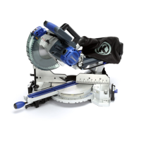
Adjusting the cutting wheel 45° to sliding
table (Fig. 34)
● Disconnect the saw from the power source.
● Loosen the bevel lock knob (PP) and move
the cutting wheel to the maximum bevel
position.
● Place the combination square to the sliding
table surface.
● If the cutting wheel is not 45° to the
groove (5), loosen the lock nut (6)
with a adjustable wrench and turn the
45° hex bolt (7) (located on top of the
cutting arm assembly as shown in
Fig. 34) in or out accordingly by using a
3 mm hex key until it is 45° to the sliding
table surface and tighten the bevel lock
knob (PP). Tighten the lock nut (6).
● Make sure that the cutting wheel does not
touch either side of the groove (5) in the
sliding table by pushing the table past the
cutting wheel.
7
6
PP
5
3
 Loading...