TT-1701 2/17
3
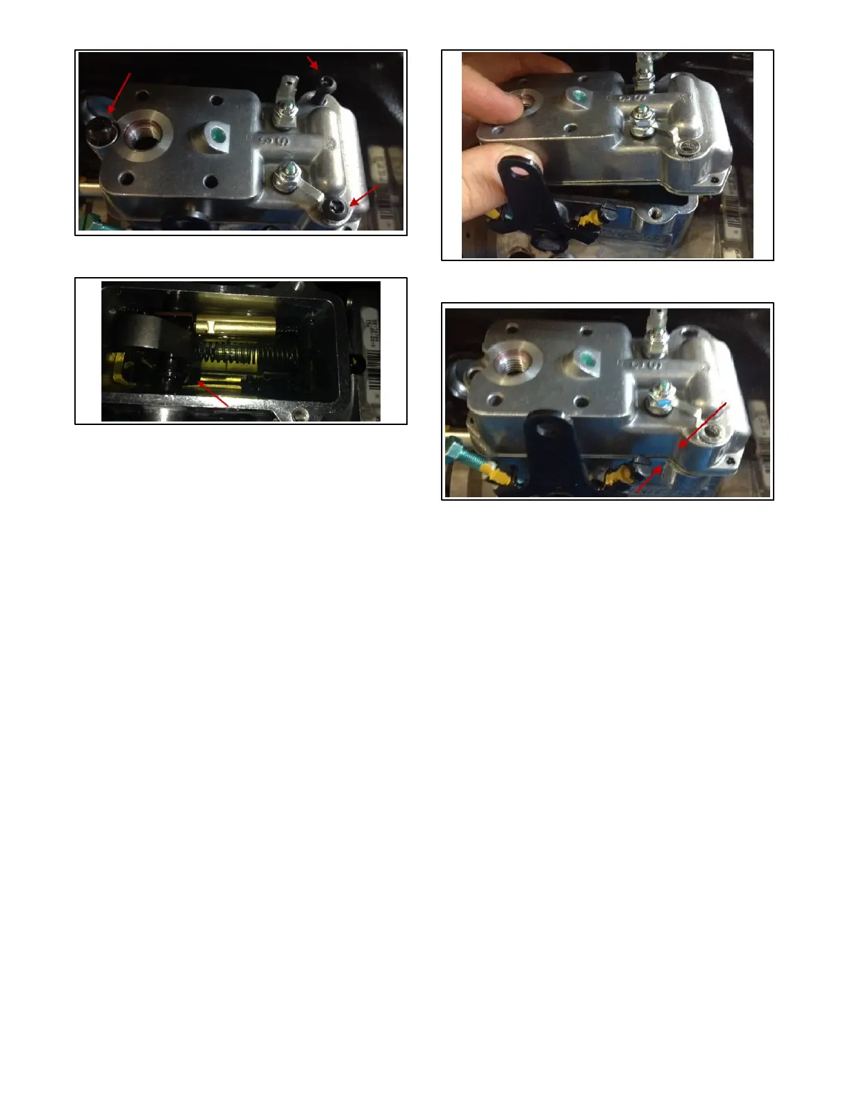
Figure 3 Actuator Screws (qty. 3)
Figure 4 Actuator
Note: To prevent any damage, properly install the
metering valve drive coupling to the governor
linkage on the pump as described below.
2.6 Install the new cover seal (part of the actuator
components) into the groove of the integrated
actuator cover assembly.
2.7 Position the actuator head similar to Figure 5.
Slightly lift the front portion of the actuator cover.
2.8 Carefully slide the integrated actuator cover
toward the rear of the pump body until the
mounting holes between the integrated actuator
cover and pump body begin to align. Once in
place, you’ll see that the actuator is offset from the
mounting holes and feel that there is spring
tension pushing on the cover. If you push on the
cover, you’ll feel the tension which means that
there is good contact with the linkage. See the
slight offset in Figure 6.
2.9 Reuse the three cover mounting screws to
assemble the integrated actuator cover to the
pump body. Tighten the screws to 4-- 5 Nm
(35--45 in. lb.).
Note: A universal joint or flex socket is needed to install
the rear-most screw.
2.10 Locate the 2 leads in the engine harness near the
governor. These leads may be yellow and orange
or blue and green (depending on the generator set
model).
Figure 5 Actuator (Cover Design Similar)
Figure 6 Actuator (Cover Design Similar)
2.11 Connect the two leads to the two screws at the
actuator. It doesn’t matter which leads attach to
which screws.
2.12 Install a new O-ring (part of the actuator
components) on the return line connector
assembly. Apply a light coating of all-purpose
grease to the O-ring and install the connector.
Tighten to 4.9--6 Nm (43--53 in. lb.).
2.13 Install the fuel return line to the return line
connector.
3. Remove the air cleaner assembly.
Removal of the air cleaner assembly is required as a
means to shut down the engine should the actuator
linkage be improperly installed in Step 2.
Note: Controllers are factory adjusted to minimum
RPM. However, for safety, the engine should be
capable of being disabled if an overspeed
condition should occur.
Note: The best practice when replacing the actuator is
to remove the air cleaner piping such that the
junction box cover can be used to cut off air
supply to the engine in the event of a runaway due
to improper governor installation.
 Loading...