TP-5592 7/96 Installation 6-21
12
45
3
6
+
5
3
6
2
4
1
1
2
3
4
5
6
7
8
9
10
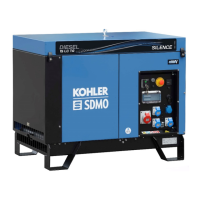
1. Use insulink or solder connection (tape to insulate)
2. Hourmeter
3. Stop
4. ON light
5. Rocker switch
6. Start
7. Generator set
8. Senders
9. Controller socket
10. Wiring harness plug
Figure 6-21. Remote Control Panel Wiring
NOTE
All wire is 16 gauge. Tape to insulate all unused lead
ends.
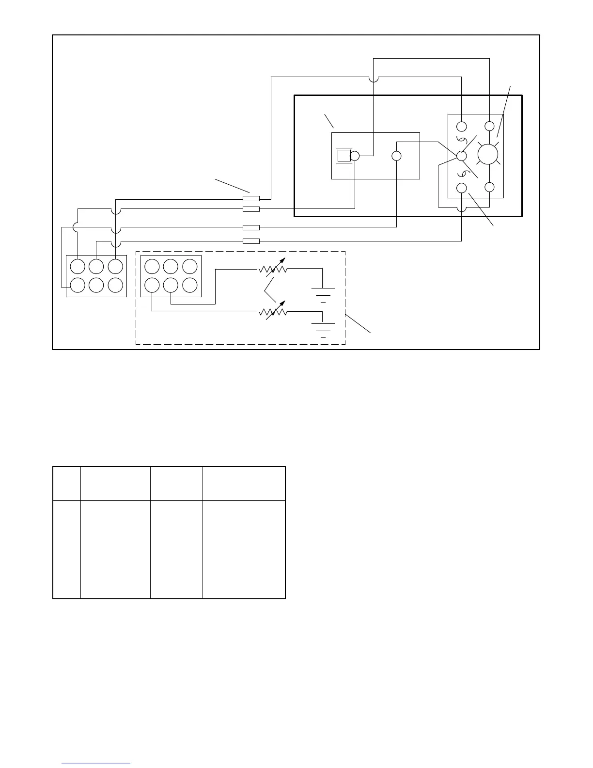
Pin
Lead
(older
models)
Lead
(newer
models)
Function
1 Black N Ground (--)
2 Tan 5 Water temperature
gauge 3
3 Lt. Blue 7C Oil pressure gauge
4 Violet 70 Generator ON (+)
5 Yellow/Red 47 Start
6 Grey/Black 43 Stop
Figure 6-22. Lead Designations