TP-5592 7/965-2 Wiring Diagrams
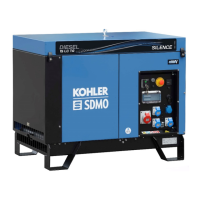
4 3 2 1
Stator Leads
L0
GRD.
L2
L1
L0 (Neutral)
Line
Side
Factory
Two-Pole
Circuit
Breaker
Ground
Load
Side
100-120/200-240 Volt,
3 Wire
60 Hz 50 Hz
L0-L1 100-120 Volt 100-120 Volt
L0-L2 100-120 Volt 100-120 Volt
L0-L2 200--240 Volt 200--240 Volt
Figure 5-2. 100-120/200-240 Volt Configuration
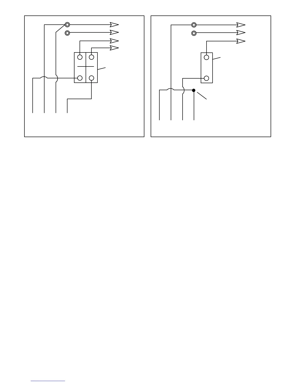
4 3 2 1
Stator Leads
L0
GRD.
L1
L0 (Neutral)
Line
Side
Single-Pole
Circuit
Breaker
Ground
Load
Side
200-220-240 Volt
2 Wire
Tape to insulate
from ground
60 Hz 50 Hz
L0-L1 not used 200-220-240 Volt
Figure 5-3. 200-220-240 Volt Configuration*