6-2 Installation TP-5592 7/96
KOHLER
1
2
3
4
5
6
7
8
9
10
11
12
13
14
15
16
17
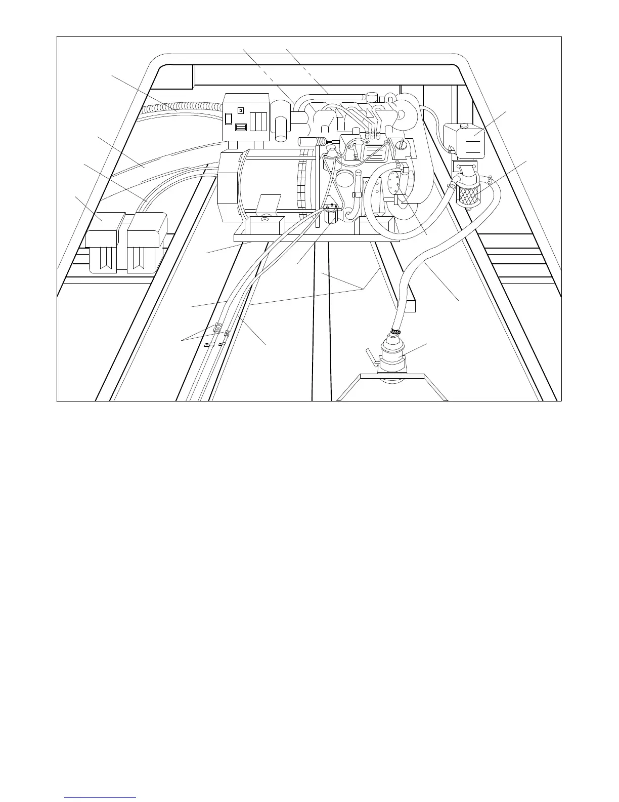
1. Exhaust mixer elbow (exhaust/water outlet) (not shown)
2. Heat exchanger (not shown)
3. Coolant recovery tank
4. Seawater strainer *
5. Seawater pump (seawater inlet)
6. Seawater line *
7. Seacock *
8. Mounting base
9. Fuel feed pump (fuel inlet) *
10. Fuel return line *
11. Hose clamps
12. Fuel supply line *
13. Mounting tray
14. Battery/battery storage box
15. Battery cables
16. Exhaust/waterline *
17. Electrical leads (AC output leads/remote start panel leads)
* Indicated components must conform to USCG Regulations.
Figure 6-1. Typical Location and Mounting
NOTE
Usetwo hose clampson each endof all flexible exhaust
hose connections.