6-14 Installation TP-5592 7/96
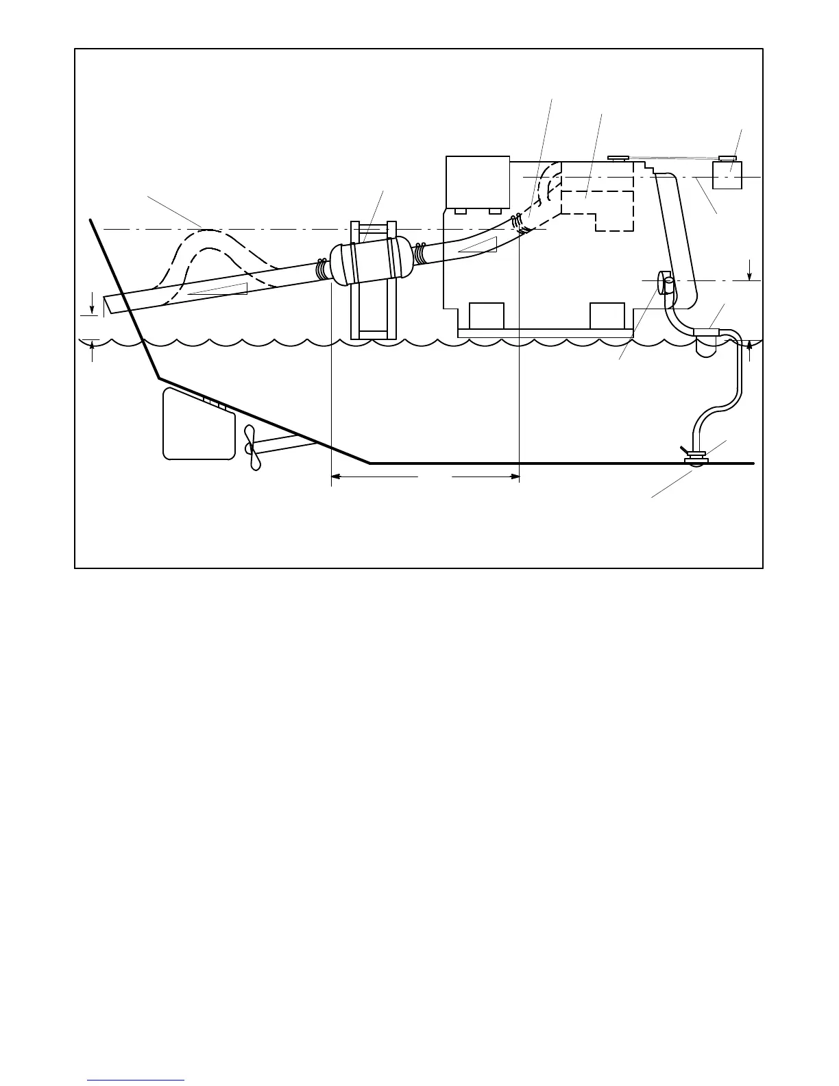
Waterline
NOTE
Numbers in Illustrations refer to callouts below
and not to dimensions.
1
2
3
4
5
6
7
8
9
10
11
12
13
14
15
1. Slight lift improves silencing (keep below level of exhaust
manifold outlet)
2. Silencer (customer-supplied)
3. Exhaust mixer elbow
4. Heat exchanger (locations vary by model)
5. Coolant recovery tank
6. Locate coolantrecovery tank at same height asheat exchanger
7. Maximum seawater pump lift of 3 ft. (1 m)
8. Seawater strainer
9. Seacock
10. Intake strainer
11. Engine-driven seawater pump
12. Minimumexhausthosepitchof0.5in.perft.(1.3cmper30.5cm)
13. Maximumdistancebetweensilencerandexhaustmixerelbowof
10 ft. (3 m)
14. Minimumexhausthosepitchof0.5in.perft.(1.3cmper30.5cm)
15. Minimumexhaustoutletdistanceabovewaterlineof4in.(10cm)
Figure 6-14. Typical Above Water Line Installation
NOTE
Usetwo hose clampson each endof all flexible exhaust
hose connections.
NOTE
Read text for complete explanation of dimensions and
other installation considerations.
NOTE
Data applies to both rear- and side-exhaust
installations.