6-16 Installation TP-5592 7/96
Waterline
7
14
13
12
15
10
9
8
17
19
11
20
6
18
4
5
21
16
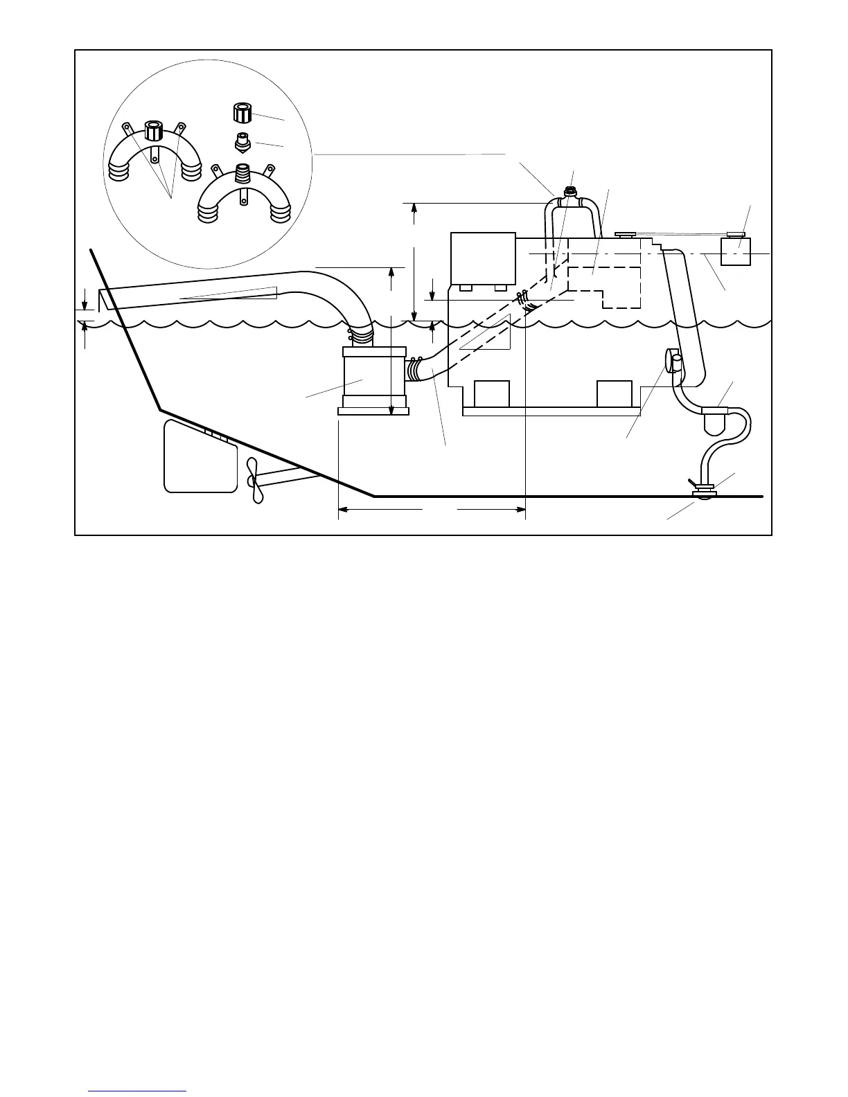
NOTE
Numbers in Illustrations refer to callouts below
and not to dimensions.
1
2
3
1. Mounting base
2. Retaining cap
3. Reed valve assembly
4. Maximum silencer vertical lift of 4 ft. (1.2 m)
5. Exhaust mixerelbow distance above waterline. If less than 9in.
(23 cm), siphon break is required.
6. Minimumsiphonbreakdistanceabovewaterlineof1ft.(30.5cm)
7. Siphon break
8. Exhaust mixer elbow
9. Heat exchanger (locations vary by model)
10. Coolant recovery tank
11. Indicates coolant recovery tank at same height as heat
exchanger
12. Seawater strainer
13. Seacock
14. Intake strainer
15. Engine-driven seawater pump
16. Minimumexhausthosepitchof0.5in.perft.(1.3cmper30.5cm)
17. Water lock (optional)
18. Maximumdistancebetweensilencerandexhaustmixerelbowof
10 ft. (3 m)
19. Silencer (customer supplied)
20. Minimumexhausthosepitchof0.5in.perft.(1.3cmper30.5cm)
21. Minimumexhaustoutletdistanceabovewaterlineof4in.(10cm)
NOTE: Read text for complete explanation of dimensions
and other installation considerations.
Figure 6-16. Typical Mid- and Below-Waterline Installation
NOTE
Usetwo hose clampson each endof all flexible exhaust
hose connections.
NOTE
Data applies to both rear- and side-exhaust
installations.