26 Section 1 Specifications TP-6953 7/19
1
2
3
4
7
8
9
10
11
12
13
14
5
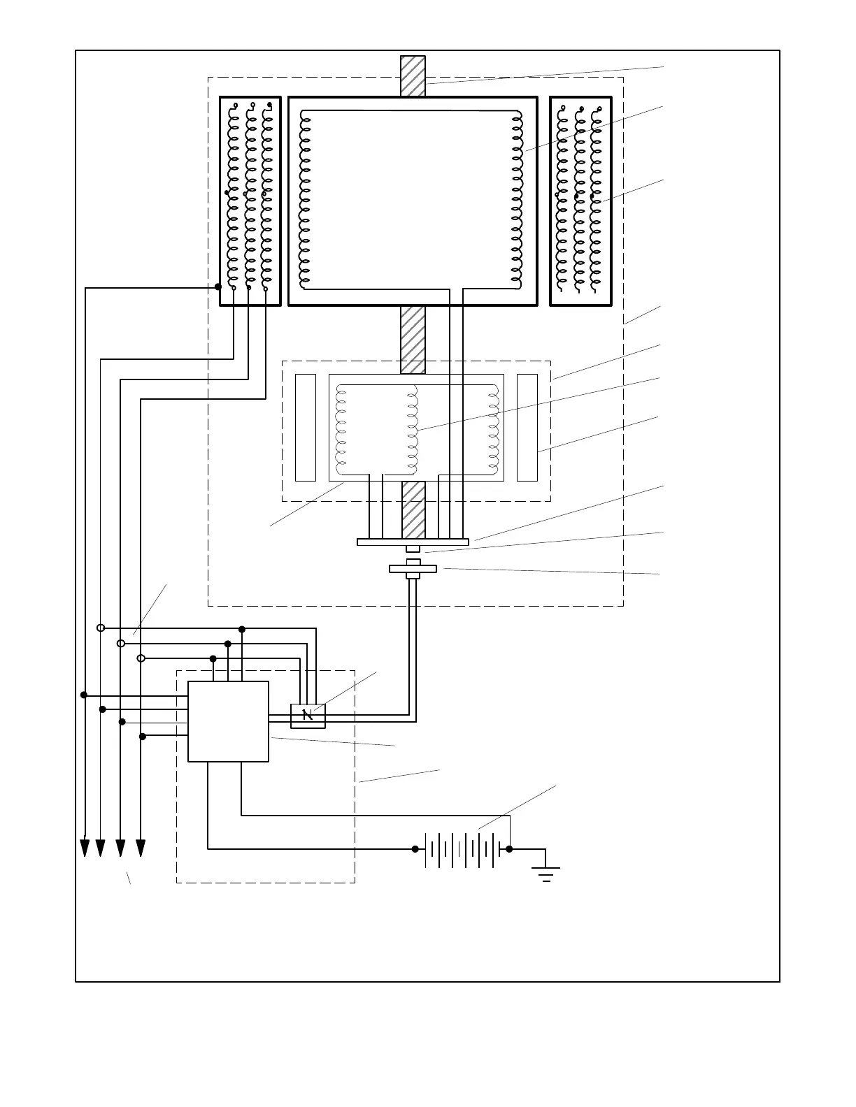
TP-6863-1
1. Rotor shaft
2. Rotor field windings (rotor assembly)
3. Stator main windings (stator assembly)
4. Alternator assembly
5. Exciter assembly
6. Exciter armature (connected to rotor)
7. Exciter armature windings
8. Exciter field magnets
9. FRX activator/photo transistor board
10. Photo transistor
11. LED optic board
12. Engine starting battery
13. Alternator protection (controller)
14. Generator set controller
15. AC voltage regulator (controller)
16. AC output leads
17. Current sensing
15
16
6
lead 3B 5B lead
NABC
17
Figure 1 -6 Alternator Schematic (40EKOZD and 35EFKOZD Models)
 Loading...