TP-6329 8/0744 Section 6 Generator Reconnection
6.2 Four-Lead (Single-Phase)
Generator Sets
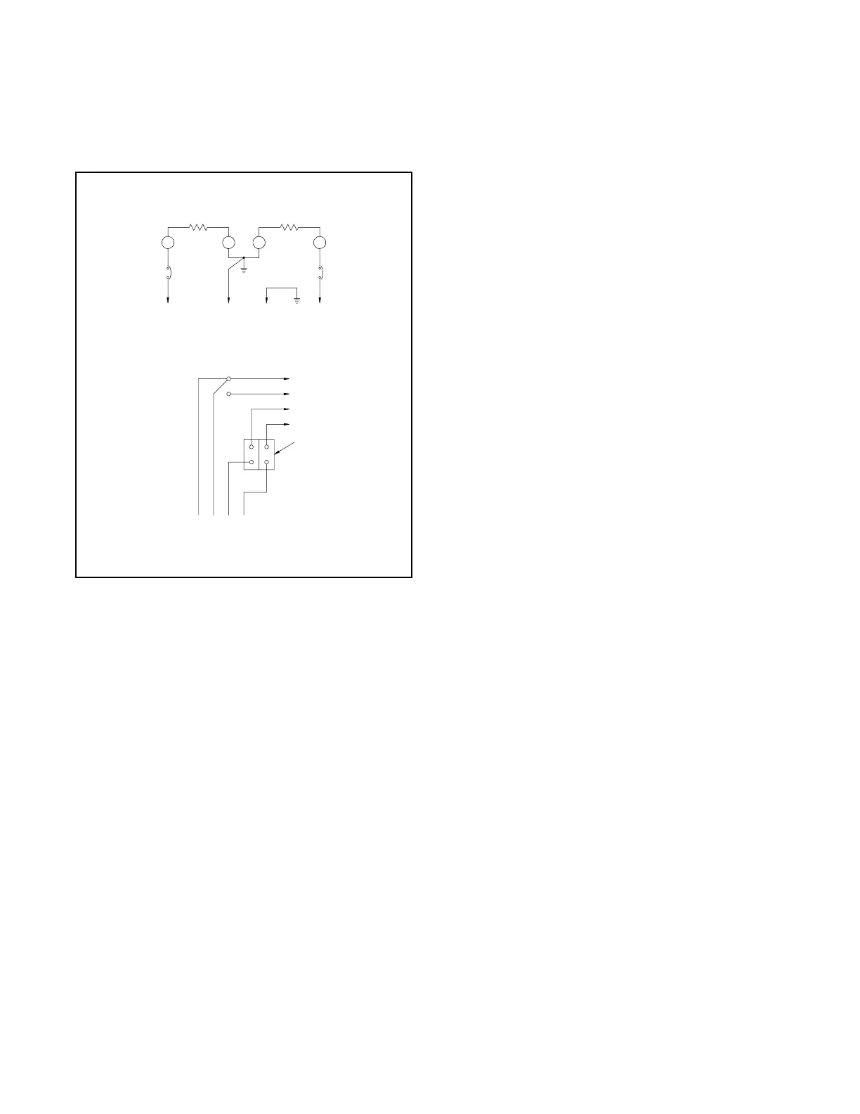
Figure 6-1 shows the factory connection for the
single-phase 120/240 V 60 Hz generator set. Single-
phase models are not reconnectable.
ADV-5857-A
3 421
100--120/200-- 240V, 60HZ
L2 L0 GRD L1
L2
L1
GRD
L0
LO (NEUTRAL)
GROUND
LOAD
LINE
SIDE
SIDE
STATOR LEADS
4231
100--120/
200--240 V O LT,
3WIRE
FACTORY
TWO--POLE
CIRCUIT
BREAKER
Figure 6-1 Single-Phase Factory Connection,
120/240 V 60 Hz
6.3 12-Lead (Three-Phase)
Generator Sets
Note: The current transformers (CTs) shown on the
following diagrams are not used on generator
sets equipped with the Advanced Digital Control
(ADC 2100).
Three-phase, 12-lead generator sets are reconnectable
to the voltages and phases shown in Figure 6-2. Use
the following procedure to reconnect the generator to
the desired voltage configuration, change the system
voltage setting, and adjust the output voltage.
Note: Equipment damage. Verify that the voltage
ratings of the transfer switch, line circuit breakers,
and other accessories match the selected line
voltage.
Reconnection Procedure
1. Place the generator set master switch in the
OFF/RESET position.
2. Disconnect engine starting battery, negative (--)
lead first. Disconnect power to battery charger, if
equipped.
3. Select desired voltage connection from Figure 6-2.
Connect the leads according to the diagram for
desired phase and voltage.
4. Reconnect generator set engine starting battery,
negative (--) lead last.
5. Follow the instructions in Section 5.3 to enter the
ADC 2100 configuration menu and check the
system configuration. Verify that the system
voltage and frequency parameter (Uu) is correct for
single-phase or three-phase configurations.
6. Connect a digital multimeter (DVM) to the
generator set output.
7. Follow the instructions in Section 5.4 to start the
generator set and enter the ADC 2100 voltage
adjustment menu.
8. Check the voltmeter for the correct voltage. Adjust
output voltage, if necessary, using the ADC 2100
voltage adjustment menu.
9. Stop the generator set after the adjustment
procedure.
 Loading...

