TP-5737 5/01 63Section 7 Component Testing and Adjustment
Testing the photo transistor circuit board. Hazardous
voltage can cause severe injury or death. When the end
cover is removed, do not expose the photo transistor circuit
board mounted on the generator set end bracket to any
external light source, as exposure to light causes high voltage.
Keep foreign sources of light away from the photo transistor
circuit board during testing. Place black electrical tape over
the LED on the circuit board before starting the generator set.
LED Circuit Board Test
1. Remove the junction box panels from the
generator end of the unit and remove the photo
transistor board/LED board cover. See Figure 7-5.
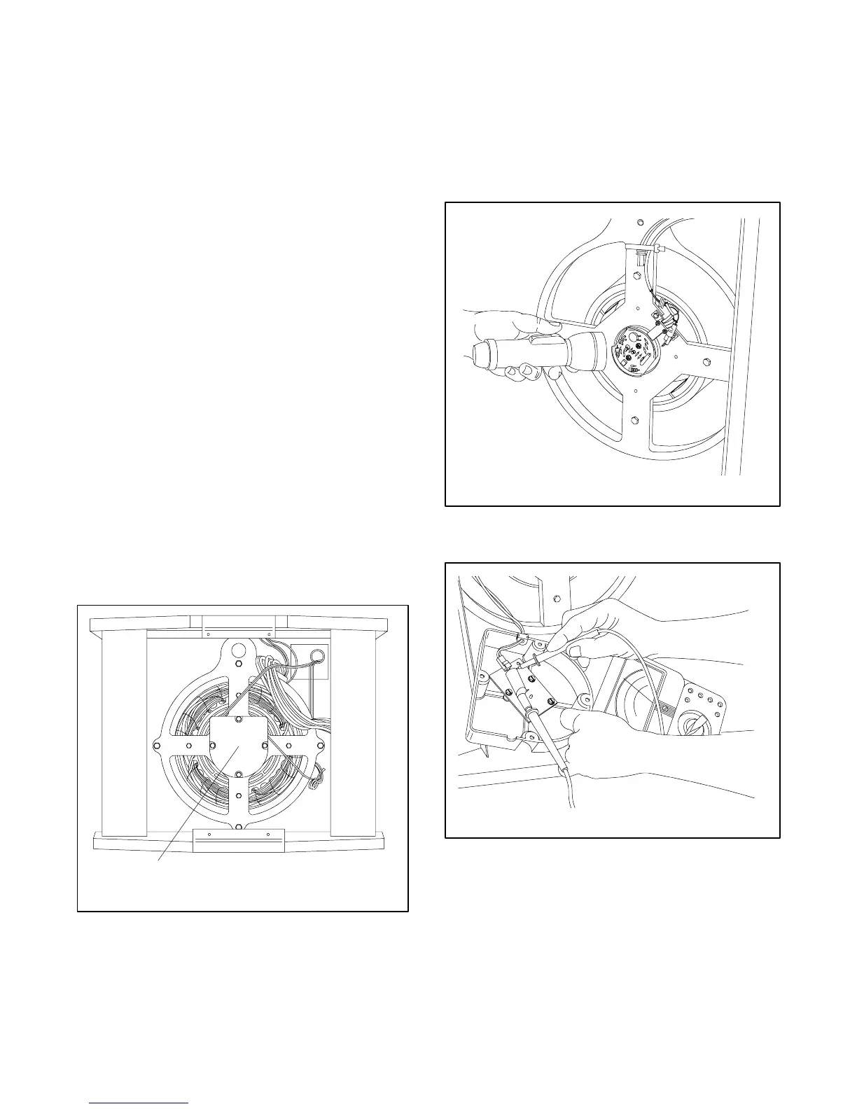
2. With the generator set running at no load, shine a
flashlight on the exposed photo transistor board.
SeeFigure7-6.
3. Observe the AC output voltmeter. The AC output
voltage should be high. Switch the flashlight off or
turn it away from the rotating photo transistor
board. The AC output voltage should be low. If
these conditions exist (high voltage while the photo
transistor board is illuminated and low voltage
while the photo transistor board is dark), then the
photo transistor board and SCR assembly are
functioning properly. The fault is likely in the wiring,
AVR, or LED circuit board. If the generator does
not respond this way to the flashlight test, the fault
is probably in the photo transistor board (PCB
assembly) or the SCR assembly. Proceed to the
tests for these items.
3-100
R8371-5
1
1. Photo transistor/LED board cover
Figure 7 -5 Panels Removed
4. With the generator set running, observe
approximately 1--2 volts DC at 3B (+) and 5B (--) at
the LED board. See Figure 7-7. Shine the flashlight
on the photo transistor. DC voltage reading should
drop, showing the AVR is functioning properly. If
voltages are not observed, refer to the AVR test.
5. Stop the generator set.
3-100
R12758-5
Figure 7 -6 LED Flashlight Test
3-094
R8936-10
Figure 7 -7 Checking LED Board
 Loading...
