Section 9
Inspection and Reconditioning
9.12
Closure Plate Assembly
Inspection
Inspect the oil seal in the closure plate and remove it if
it is worn or damaged. Refer to Install Closure Plate
Oil Seal in Section 10 for new oil seal installation.
Inspect the main bearing surface for wear or damage
(refer to Section 1, Specifi cations, Tolerances, and
Special Torque Values). Replace the bearing or
closure plate assembly if required.
Oil Pump Assembly
Disassembly
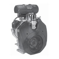
1. Remove the three hex fl ange screws securing
the oil pump housing including the relief valve
baffl e, and the single screw with clamp for the
pickup tube. See Figure 9-13.
2. Remove the oil pump housing and pickup tube
from the closure plate.
3. Remove the oil pump gerotor gears from the
closure plate recess.
4. Remove the oil pickup by pulling it free from the
oil pump body.
5. The relief valve is a one-piece style, staked to
the oil pump housing; removal should not be
a empted, nor is internal servicing possible. If a
problem with the relief valve is encountered, the
oil pump should be replaced. See Figure 9-15.
Mounting
Screws
Relief
Valve
Baffl e
Oil
Pump
Pickup
Tube
Figure 9-13. Removing Oil Pump.
Inspection
Inspect the oil pump housing, gerotor gears, and
closure plate recess for nicks, burrs, wear, or any
visible damage. Inspect the inlet seal for the pickup
tube in the housing. If any parts are worn or damaged,
replace the seal, oil pump or closure plate as required.
Reassembly
1. Make sure the recess in the closure plate for the
oil pump gerotor gears is clean.
2. Lubricate the oil pump gerotor gears with grease
(Lubriplate
®
100 or equivalent), and install into
the recess. See Figure 9-14.
Figure 9-14. Installing and Lubricating Oil Pump
Gerotor Gears.
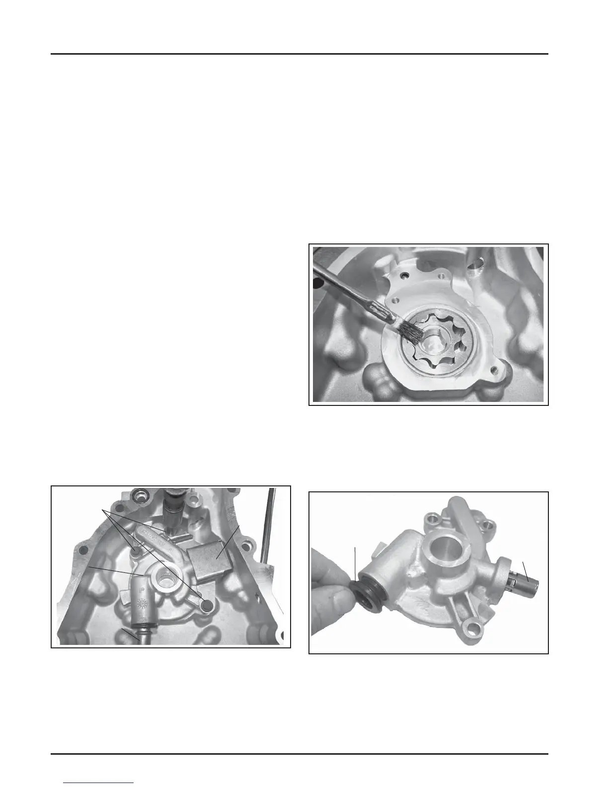
3. Lightly lubricate with oil and install the inlet seal
into the oil pump housing until it is fully seated.
See Figure 9-15.
Inlet
Seal
Relief
Valve
Figure 9-15. Installing Inlet Seal in Oil Pump
Housing.
 Loading...