5.6
Section 5
Fuel System and Governor
Low Idle Speed (RPM) Adjustment
1. Low Idle Speed (RPM) Se ing: Place the thro le
control in the idle or slow position. Set the low
idle speed approximately 300 RPM* less than
the intended or specifi ed Governed Idle Speed,
by turning the low idle speed adjusting screw
in or out. Check the speed using a tachometer.
IMPORTANT: The Governed Idle Speed
Adjustment must follow any rese ing of the
Low Idle Speed.
*NOTE: The actual low idle speed depends on
the application. Refer to the equipment
manufacturer’s recommendations.
The low idle speed for basic engines
is 1200 RPM. To ensure best results
when se ing the low idle fuel needle,
the low idle speed should be 1200 RPM
(± 75 RPM).
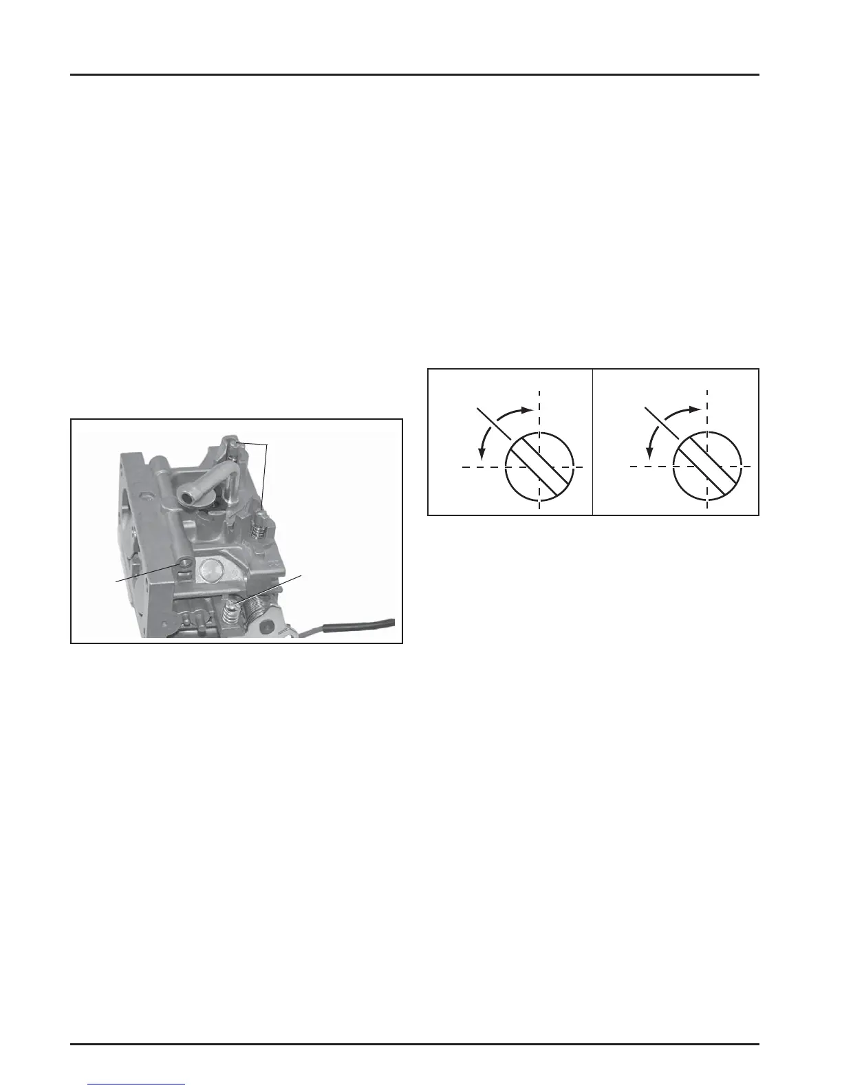
Figure 5-5. Carburetor Adjustment Locations.
Low Idle Fuel Adjustment
NOTE: Engines will have fi xed low idle or limiter
caps on the two idle fuel adjusting needles.
Step 3 can only be performed within the
limits allowed by the cap. Do not a empt to
remove the limiter caps.
1. Start the engine and run at half thro le for 5 to 10
minutes to warm up. The engine must be warm
before doing Steps 2, 3, and 4.
2. Place the thro le control into the idle or slow
position. Adjust the low idle speed to 1200 RPM.
Follow the Adjusting the Low Idle Speed (RPM)
procedure.
3. Low Idle Fuel Needle(s) Se ing: Place the
thro le into the idle or slow position.
a. Turn one of the low idle fuel adjusting
needles out (counterclockwise) from the
preliminary se ing until the engine speed
decreases (rich). Note the position of the
needle. Now turn the adjusting needle in
(clockwise). The engine speed may increase,
then it will decrease as the needle is turned
in (lean). Note the position of the needle. Set
the adjusting needle midway between the
rich and lean se ings. See Figure 5-6.
b. Repeat the procedure on the other low idle
adjustment needle.
4. Recheck/adjust the Low Idle Speed (RPM) to the
specifi ed se ing.
Figure 5- 6. Optimum Low Idle Fuel Settings.
Governed Idle System
A governed idle control system is used to maintain a
desired idle speed regardless of ambient conditions
(temperature, parasitic load, etc.) that may change.
An outer secondary spring connected between the
governor lever and the governed idle adjuster on the
main bracket establishes the governed idle speed. See
Figure 5-7.
Governed Idle Speed Adjustment
1. Make sure the governed idle spring is in the outer
hole in the governor lever and the hole in the
governed idle (outer) adjuster. See Figure 5-7.
2. Make sure the governor spring is in the inner slot
of the governor lever and the hole in the high
speed (inner) adjuster. See Figure 5-7. Pull the
governor lever away from carburetor to the limit
of its travel and check that the governor spring is
loose and not under any tension. See Figure 5-8.
Turn the high-speed (RPM) adjustment screw
counter-clockwise (if required) until spring is
loose.
Lean
Rich
Adjust to
Midpoint
Lean
Rich
Adjust to
Midpoint
Left Side
Right Side
Low Idle Fuel Adjusters
(with Limiters)
Low Idle
Speed (RPM)
Adjustment
Screw
Bowl
Vent
 Loading...