10.4
Section 10
Internal Components
Hard starting, or loss of power accompanied by high
fuel consumption may be symptoms of faulty valves.
Although these symptoms could also be attributed to
worn rings, remove and check the valves first. After
removal, clean the valve heads, faces, and stems with a
power wire brush.
Then, carefully inspect each valve for defects such as
warped head, excessive corrosion, or worn stem end.
Replace valves found to be in bad condition.
Valve Guides
If a valve guide is worn beyond specifications, it will
not guide the valve in a straight line. This may result
in burnt valve faces or seats, loss of compression, and
excessive oil consumption.
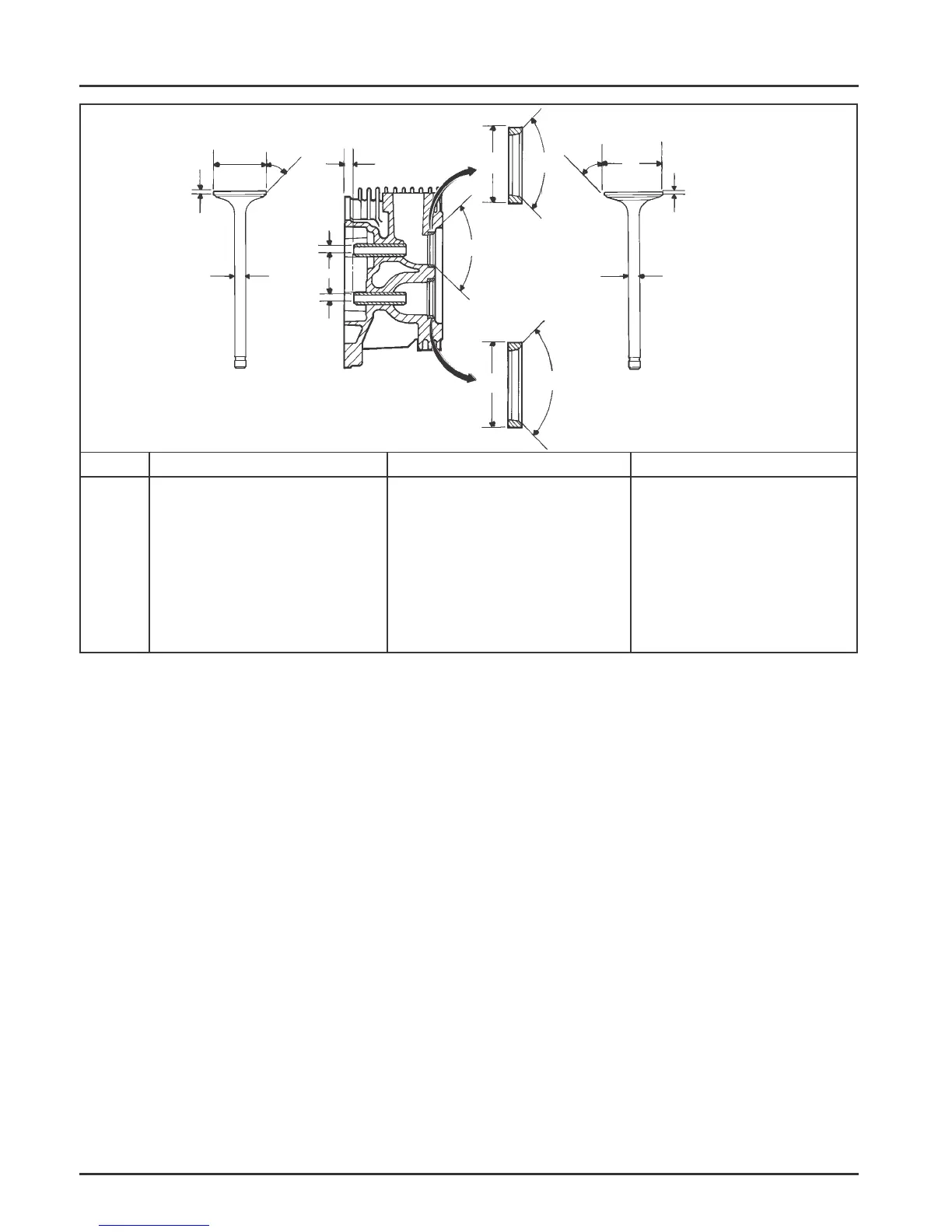
Dimension
Intake
Exhaust
A
B
C
D
E
F
G
H
Seat Angle
Insert O.D.
Guide Depth
Guide I.D.
Valve Head Diameter
Valve Face Angle
Valve Margin (Min.)
Valve Stem Diameter
89°
37.987/38.013 mm
6.5 mm
7.033/7.058 mm
35.63/35.37 mm
45°
1.5 mm
6.982/7.000 mm
89°
34.013/33.987 mm
6.5 mm
7.033/7.058 mm
31.63/31.37 mm
45°
1.5 mm
6.970/6.988 mm
To check valve guide to valve stem clearance,
thoroughly clean the valve guide and, using a split-
ball gauge, measure the inside diameter. Then, using
an outside micrometer, measure the diameter of the
valve stem at several points on the stem where it
moves in the valve guide. Use the largest stem
diameter to calculate the clearance. If the clearance
exceeds 7.134 mm (0.2809 in.) on intake or 7.159 mm
(0.2819 in.) on exhaust valve, determine whether the
valve stem or the guide is responsible for the excessive
clearance.
If the valve stem diameter is within specifications,
then recondition the valve guide.
Reconditioning Valve Guide
The valve guides in the cylinder head are not
removable. Use a 0.25 mm (0.010 in.) O/S reamer (See
Section 2).
Intake Valve
C
D
D
H
G
Exhaust Valve
E
F
Exhaust
Insert
Intake
Insert
G
H
A
A
B
B
A
F
E
Figure 10-3. Valve Details.
 Loading...


