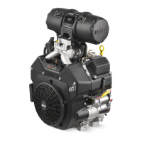
Do you have a question about the Kohler COMMAND CH18-745 and is the answer not in the manual?
Essential safety guidelines for operating and maintaining the engine.
Details on how to identify engine model, specification, and serial numbers.
Guidelines for selecting and using the correct engine oil for optimal performance.
Advice on choosing and using appropriate fuel for the engine.
Schedule and instructions for routine engine maintenance.
Procedure for properly storing the engine for extended periods.
Technical drawings showing engine dimensions with standard air cleaner.
Key technical specifications including power, torque, bore, stroke, and weight.
Detailed specifications for camshaft dimensions and clearances.
Specifications for connecting rod clearances and fastener torque.
Specifications for cylinder bore ID, wear limits, and out-of-round.
Spark plug gap, torque, and ignition module air gap specifications.
Specifications for piston-to-pin clearance, pin bore, and piston OD.
Torque recommendations for metric fasteners in standard applications.
Instructions for fabricating useful tools from common materials.
Information on using a cylinder leakdown tester as a compression test alternative.
Approved RTV silicone sealants for crankcase and closure plate gaskets.
Recommended lubricant for new camshaft and lifter break-in.
Guide to diagnosing and resolving common engine starting and running issues.
Common causes and checks for when the engine does not crank.
Common causes for difficulty in starting the engine.
Causes of engine overheating and potential damage.
Common reasons for a decrease in engine power output.
Procedure and interpretation for testing crankcase vacuum.
Explanation of the cylinder leakdown test and its application.
Interpretation of results from a cylinder leakdown test.
Routine service and inspection of the standard air cleaner.
Instructions for servicing the precleaner element.
Procedure for replacing the paper air cleaner element.
Exploded view illustrating components of the standard air intake system.
Checks for cover, base, and breather tube for proper function and condition.
Procedure for servicing the heavy-duty air cleaner element.
Importance of keeping air intake and cooling system clean.
Lists the main components of a typical carbureted fuel system.
Guidelines for using appropriate fuel and general recommendations.
Overview of fuel pump types (pulse and mechanical) and their operation.
Procedures for replacing pulse and mechanical fuel pumps.
Description of Keihin carburetors used, including variations.
Common problems and their probable causes related to carburetors.
Function and testing procedure for the fuel shut-off solenoid.
General information on carburetor adjustments, including pre-compliance models.
Step-by-step guide for adjusting low idle speed and fuel mixture.
Procedure for checking and adjusting the carburetor float level.
Step-by-step instructions for disassembling the carburetor.
Guidelines for inspecting and repairing carburetor components.
Exploded view of the carburetor showing all components and their part numbers.
Overview of the centrifugal flyweight mechanical governor system.
Explanation of how the governor mechanism works to control engine speed.
Procedure for initial governor adjustment on carburetor-equipped engines.
Method for adjusting governor sensitivity to prevent surging or speed drops.
Procedure for adjusting the engine's maximum high speed RPM.
Overview of the electronic governor system components.
Procedure for adjusting the DLA for proper throttle plate movement.
Steps to troubleshoot EFI system issues related to starting and expected speed.
Lists the components of a typical "liquid withdrawal" LPG fuel system.
Explanation of how the LPG fuel system functions.
Initial checks for common LPG system issues.
Troubleshooting specific problems like hard starting, rough idle, and stalling.
Overview of LPG carburetor adjustments and factory presets.
Procedure for adjusting the idle speed on LPG engines.
Procedures for cleaning Impco and Nikki carburetors.
Guidelines for inspecting LPG carburetor bodies and shafts.
Steps for reassembling the Impco carburetor.
Procedure for setting the idle speed clamp bracket position.
Procedure for setting the high speed stop collar position.
Functional test and filter service for the electric lock-off/filter assembly.
Maintenance and service of the vaporizer assembly.
Overview of Impco and Nikki LPG regulators and their operation.
Detailed explanation of the Impco (Beam) regulator's operation.
Explanation of the Nikki regulator's primary chamber function.
Explanation of the Nikki regulator's secondary chamber function.
Maintenance recommendations for LPG regulators, including draining.
Recommended service intervals and procedures for Impco and Nikki regulators.
Safety warnings about high fuel pressure and procedures for priming.
Guidelines for fuel type and general recommendations for EFI systems.
Lists the principal components of the EFI system.
Explanation of how the EFI system manages fuel and ignition for peak performance.
Critical notes for servicing the EFI system, emphasizing cleanliness and safety.
Overview of the ECU, its function, and types.
Details on the TPS, its function, and the critical initialization procedure.
Function and testing of the engine speed sensor.
Testing procedures for the engine speed sensor, including resistance checks.
General information about the TPS and service testing procedures.
Critical procedure to reestablish the relationship between ECU and TPS.
Detailed steps for TPS initialization on specific ECU types.
"Auto-Learn" TPS initialization procedure for the 32-pin ECU.
Function and testing procedures for the engine oil temperature sensor.
Function, operation, and service checks for the oxygen sensor.
Detailed tests for oxygen sensor voltage output and resistance.
Function, operation, and testing of the electrical relay.
Description of fuel injector types and mounting.
Methods for checking injector operation and common problems.
Procedures for testing injector resistance and circuit continuity.
Information on servicing and testing the ignition system components.
Specifications for EFI engine spark plugs, including type and gap.
Role of the wiring harness and connector details for EFI systems.
Lists and illustrates fuel system components like pumps and battery charging.
Information on servicing and replacing the electric fuel pump.
Description and illustration of external and internal fuel pressure regulators.
Procedures for accessing and replacing external and internal fuel pressure regulators.
Recommended service interval for the in-line fuel filter.
Description and installation notes for the fuel rail and high-pressure fuel line.
Overview and service of the throttle body/intake manifold assembly.
General information on adjusting the idle speed for EFI engines.
Detailed steps for performing the idle speed adjustment.
Criticality and overview of initial governor adjustment for EFI engines.
Procedure to check the governor and throttle linkage adjustment.
Steps for setting the initial governor adjustment.
General advice for troubleshooting EFI system problems.
Guide to diagnosing common EFI engine starting and running issues.
General information on the EFI electrical system, voltage requirements, and connections.
How the ECU monitors operation, activates MIL, and stores fault codes.
Procedure for accessing diagnostic codes via key switch and MIL.
Table detailing components connected to each pin of the 35-pin ECU connector.
Wiring diagram for relays and general installation precautions.
Table detailing components connected to each pin of the 24-pin ECU connector.
Table detailing components connected to each pin of the 32-pin ECU connector.
Procedures for quick testing and priming the EFI fuel system.
Troubleshooting the EFI fuel system and understanding fault codes.
Illustration of how diagnostic codes are displayed via MIL blinking.
Procedure for clearing stored fault codes after repairs.
Table summarizing blink codes, failure descriptions, and applicable ECUs.
Details for fault code 21 related to the engine speed sensor.
Details for fault code 22 related to the throttle position sensor.
Details for fault code 23 related to ECU internal memory issues.
Details for fault code 24 related to missing engine speed sensor signal.
Details for fault code 31 indicating a lean condition.
Details for fault code 32 related to no change in oxygen sensor signal.
Details for fault code 33 indicating a rich mixture condition.
Details for fault code 34 related to fuel adaptation control limits.
Details for fault code 42 related to the oil temperature sensor.
Details for fault codes 43 & 44 related to TPS auto-learn initialization failure.
Details for fault code 51 related to injector #1 circuit issues.
Details for fault code 52 related to injector #2 circuit issues.
Details for fault code 55 related to the Malfunction Indicator Light circuit.
Details for fault code 56 related to the fuel pump relay circuit.
Flow chart for troubleshooting the EFI system step-by-step.
Visual representation of the EFI troubleshooting process.
Aids for troubleshooting when the MIL does not illuminate.
Aids for troubleshooting based on detected fault codes.
Aids for troubleshooting when the MIL remains on during engine running.
Aids for troubleshooting speed sensor issues.
Aids for troubleshooting fuel pump issues.
Aids for troubleshooting relay issues.
Aids for troubleshooting ignition system issues.
Aids for troubleshooting electrical fuel system issues.
Aids for troubleshooting fuel system pressure issues.
Aids for troubleshooting basic engine problems.
Overview of the full pressure lubrication system and its components.
Guidelines for selecting and using the correct engine oil.
Procedure for checking the engine oil level before each use.
Procedures for changing engine oil and filter.
Procedure for replacing the oil filter.
Instructions for cleaning and servicing the oil cooler.
Overview of the optional Oil Sentry™ oil pressure monitor switch.
Instructions for installing the Oil Sentry™ pressure switch.
Procedures for installing and testing the Oil Sentry™ switch.
Procedures for removing and installing the starter assembly.
Steps for replacing the starter rope without full disassembly.
Detailed steps for installing the starter rope and handle.
Instructions for replacing the starter pawls and associated parts.
Step-by-step instructions for disassembling the retractable starter.
Notes on the position and removal of the spring and keeper assembly.
Guidelines for inspecting and servicing starter components.
Step-by-step instructions for reassembling the retractable starter.
Information on spark plug types, gap, and service.
Visual guide to identifying normal and fouled spark plug conditions.
Recommendations for battery capacity based on temperature.
Guidelines for battery maintenance and safety precautions.
Procedure for testing battery voltage during cranking.
Overview of the CD ignition system and its components.
Explanation of Capacitive Discharge (Fixed Timing) ignition system operation.
Diagram of the CD ignition system with spark advance.
Block diagram illustrating the operation of the spark advance module.
Explanation of how the SMART-SPARK™ system operates.
General notes on troubleshooting CD ignition systems.
High-energy spark warning and precautions.
Procedure to isolate ignition system problems on standard systems.
Procedures for isolating ignition problems on SMART-SPARK™ engines.
List of special tools and specifications required for SMART-SPARK™ testing.
Procedure to verify ignition system issues.
Procedure for testing spark on SMART-SPARK™ systems.
Procedure for checking ignition timing advance.
Procedure for testing ignition modules and their connections.
Table of resistance values for testing ignition modules.
Procedure for testing the Spark Advance Module (SAM).
Detailed instructions for testing the SAM using a tester.
Important notes and procedures for ASAM and DSAM testing.
Overview of charging systems (15, 20, 25 amp regulated, 3 amp unregulated).
Guidelines to avoid damage to electrical systems during service.
Wiring diagram for regulated charging systems.
Wiring diagram for the 3 amp unregulated charging system.
Procedure for testing 15 amp rectifier-regulators using a tester.
Instructions for operating the rectifier-regulator tester and interpreting lights.
Procedure for testing 20/25 amp rectifier-regulators using a tester.
Procedure for testing original style 25 amp rectifier-regulators.
Procedure for testing 4 amp unregulated rectifiers.
Diagram showing connections for testing the charging system.
Guide to diagnosing battery charging problems for regulated systems.
Guide to diagnosing charging problems for the 3 amp unregulated system.
Overview of electric starting motors, including inertia and solenoid shift types.
Important precautions to prevent starter motor damage.
Operation, troubleshooting, and repair of inertia drive starters.
Guide to diagnosing and correcting starting problems.
Explanation of how inertia drive starters operate.
Service recommendations for inertia drive starters.
Procedures for servicing the drive components of Style "A" starters.
Procedures for servicing the drive components of Style "B" starters.
Steps for installing the retaining ring on the starter.
General instructions for starter disassembly.
Procedure for replacing brushes and brush holder in Style "A" end caps.
Instructions for assembling Style "A" commutator end caps with brushes.
Importance of aligning match marks on starter components.
Instructions for assembling Style "B" commutator end caps.
Overview of solenoid shift starter types.
Explanation of how solenoid shift starters operate.
Step-by-step instructions for disassembling solenoid shift starters.
Service recommendations for solenoid shift starters.
Step-by-step instructions for reassembling solenoid shift starters.
Instructions for disassembling Delco-Remy starters.
Instructions for removing solenoid mounting screws.
Instructions for removing the plunger and thru bolts.
Steps for removing the commutator end plate assembly.
Steps for removing the starter frame.
Instructions for removing the drive lever bushing and armature.
Instructions for removing the retaining ring.
Exploded view of the Delco-Remy starter components.
Procedures for inspecting brushes and commutator for wear.
Procedures for checking armature continuity and insulation.
Inspection points for the drive pinion's wear and damage.
Inspection of brushes and springs for wear and fatigue.
Inspection of armature commutator and windings.
Check for completeness and wear of the shift fork.
Procedure for replacing starter brushes and springs using a kit.
Service recommendations for solenoid shift starters.
Steps for reassembling the starter after service.
Instructions for installing the thrust washer.
Steps for installing the armature and pivot lever.
Instructions for installing the backup washer and grommet.
Steps for installing the starter frame and drain tube.
Procedures for installing brush holder assemblies with tools.
Notes on using the brush installation tool and retainer clips.
Procedures for installing the brush holder assembly with tools.
Torque specifications for thru bolts and brush holder screws.
Instructions for connecting the positive brush lead.
Critical warning about accidental starts and disabling the engine before work.
General instructions for cleaning parts and using cleaners safely.
Suggested order for complete engine disassembly.
Instructions for disconnecting spark plug leads.
Procedure for safely shutting off the fuel supply.
Procedures for draining engine oil and removing the oil filter.
Instructions for removing the oil cooler assembly.
Procedure for removing the exhaust muffler.
Steps for removing the air cleaner assembly.
Instructions for removing the breather tube.
Procedures for removing pulse and mechanical fuel pumps, including safety warnings.
Procedure for removing the mechanical fuel pump.
Steps for removing the control panel, if equipped.
Procedures for removing throttle and choke control components.
Steps for removing external governor controls.
Procedure for removing the carburetor, including safety warnings.
Steps for disconnecting and removing ignition modules.
Procedures for removing the intake manifold and associated components.
Procedure for removing spark plugs from cylinder heads.
Procedures for removing cylinder heads and hydraulic lifters.
Procedures for removing and marking hydraulic lifters for proper reinstallation.
Steps for disassembling cylinder heads, including valve train components.
Procedures for removing the grass screen and fan.
Instructions for removing the flywheel using special tools.
Steps for removing the stator and backing plates.
Procedures for removing stator and backing plates.
Steps for removing the closure plate assembly, including breaking seals.
Procedure for removing the camshaft and shim.
Procedures for removing connecting rods, pistons, and rings, with notes on marking.
Procedure for removing the crankshaft.
Procedures for removing the governor cross shaft.
Procedure for removing the flywheel end oil seal.
Explanation of the ACR mechanism and its operation.
Procedures for inspecting and servicing the camshaft.
Procedures for inspecting the crankshaft and its components.
Inspecting crankshaft surfaces and procedures for removing/installing crankpin plug.
Checking gasket surfaces and main bearings of the crankcase.
Procedures for inspecting cylinder bores and honing for resizing.
Importance and procedure for cleaning cylinder bores after machining.
Procedure for accurately measuring piston-to-bore clearance.
Inspecting the flywheel for cracks and keyway damage.
Inspecting cylinder head flatness and valve mechanism parts.
Detailed valve dimensions and inspection criteria for defects.
Visual examples of normal, bad, and coked valve conditions.
Explains causes of excessive combustion temps, gum deposits, stem corrosion, and overheating.
Checking valve guide-to-stem clearance and wear limits.
Procedures for lapping valves and installing intake valve stem seals.
Inspection of pistons and cylinder walls for scuffing and scoring.
Explains causes of ring failure, piston scuffing, scratches, detonation, and preignition.
Information on replacement piston and ring availability and key points for ring servicing.
Step-by-step procedure for installing new piston rings.
Detailed procedures for installing oil control, middle, and top compression rings.
Inspecting connecting rods for wear and clearances.
Inspecting hydraulic lifters and procedures for bleeding excess oil.
Inspecting the closure plate and its main bearing surface.
Inspecting governor gear teeth and weights.
Procedures for removing and installing the governor gear assembly.
Procedures for disassembling the oil pump assembly.
Inspecting oil pump components and reassembly procedures.
Procedure for replacing the governor cross shaft oil seal.
General guidelines for engine reassembly, emphasizing torque values and cleanliness.
Suggested order for complete engine reassembly.
Procedure for installing the flywheel end oil seal.
Procedures for installing the governor cross shaft, including end play adjustment.
Procedure for installing the crankshaft into the crankcase.
Procedures for installing connecting rod/piston assemblies, noting orientation and lubrication.
Torque values for different types of connecting rod bolts.
Procedure for installing the camshaft, including lubrication and timing marks.
Procedures for checking and adjusting camshaft end play.
Procedures for checking and adjusting camshaft end play using shims.
Information on thrust bearings, washers, and shims for crankshaft end play.
Correct sequence for installing thrust bearing, washer, and shim.
Procedure for installing the closure plate oil seal.
Procedures for installing the closure plate using sealant and fasteners.
Procedures for installing the stator and backing plates.
Important precautions and procedures for installing the flywheel.
Procedures for routing stator leads and installing backing plates.
Procedures for installing the flywheel, key, and fastener.
Procedure for installing the fan onto the flywheel.
Procedure for installing the plastic grass screen.
Procedures for installing supports for metal grass screens.
Procedures for preparing and installing hydraulic lifters.
Importance of matching cylinder barrel and head numbers.
Notes on intake valve stem seals and their replacement.
Steps for assembling cylinder heads with valves and springs.
Procedures for installing cylinder heads, noting hardware and component intermixing.
Torque specifications and sequence for cylinder heads secured with screws or studs.
Procedure for installing new mounting studs to specified heights.
Procedures for installing push rods and rocker arms, noting interchangeability.
Procedure for installing new spark plugs and torquing them.
Procedures for installing ignition modules, noting SMART-SPARK™ differences.
Procedure for setting the ignition module air gap.
Procedures for installing the intake manifold with gaskets/O-rings and torque sequence.
Procedures for connecting leads to standard and SMART-SPARK™ ignition modules.
Procedures for installing breather cover, inner baffles, and related components.
Instructions for installing inner baffles using screws.
Procedures for installing blower housing and outer baffles, noting screw alignment.
Torque specifications for short screws and baffle mounting screws.
Procedure for attaching the metal grass screen.
Procedures for reinstalling and connecting the rectifier-regulator.
Procedure for reinstalling the SAM module.
Procedure for reinstalling the SAM module.
Procedures for installing the electric starter motor and connecting leads.
Procedure for installing the fuel pump, including safety warnings.
Procedure for installing the carburetor, including safety warnings and ground lead connection.
Procedure for installing the governor lever onto the governor cross shaft.
Procedure for adjusting the governor lever position.
Procedures for connecting choke linkage and installing control bracket.
Procedure for connecting the governor spring to the lever.
Chart for setting governor lever hole position based on desired RPM.
Charts for setting governor lever position for different engine series.
Procedures for installing valve covers, noting different designs and torque sequences.
Reference to Section 4 for air cleaner reassembly procedure.
Procedure for connecting the fuel inlet line.
Steps for installing air cleaner base and breather hose.
Procedure for reinstalling the oil cooler and its nipple adapter.
Procedures for installing the oil filter and filling the crankcase with oil.
Procedures for reinstalling the oil dipstick and fill cap.
Procedure for connecting the spark plug leads.
Final checks before starting the engine after reassembly.
Recommendations for testing the engine after reassembly.
Overview of the wet disc type clutch.
Information on oil type, level, and change intervals for the clutch.
Procedure for adjusting clutch engagement pressure.
Procedures for reconditioning the clutch assembly.
| Horsepower | 18 hp |
|---|---|
| Compression Ratio | 8.5:1 |
| Ignition System | Electronic |
| Starter Type | Electric |
| Governor Type | Mechanical |
| Valve Configuration | OHV (Overhead Valve) |
| Engine Type | 4-cycle, gasoline, OHV |
| Fuel System | Carburetor |
| Oil Capacity | 1.9 L (2.0 US qt) |
| Cooling System | Air-cooled |
| Lubrication | Full pressure lubrication with full-flow filter |
| Max Power | 13.4 kW |
