9.13
Section 9
Disassembly
9
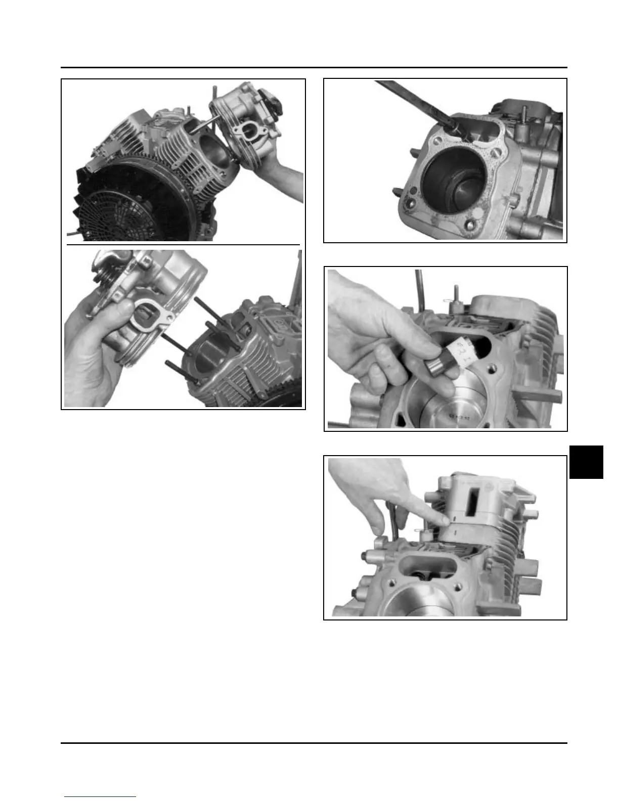
Figure 9-48. Removing Hydraulic Lifter.
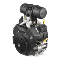
Figure 9-47. Removing Cylinder Head Assembly.
4. Remove the lifters from the lifter bores. Use
Hydraulic Lifter Tool (SPX Part No. KO1044) Do
not use a magnet to remove lifters. Mark the
lifters by location, as either intake or exhaust and
cylinder 1 or 2. Hydraulic lifters should always be
reinstalled in the same position. See Figures 9-48
and 9-49.
NOTE: The exhaust lifters are located on the output
shaft side of the engine while the intake lifters
are located on the fan side of the engine. The
cylinder head number is embossed on the
outside of each cylinder head. See Figure
9-50.
Figure 9-49. Mark Position of Hydraulic Lifters.
Figure 9-50. Match Marks on Cylinder Barrel and
Heads.