9.11
Section 9
Disassembly
9
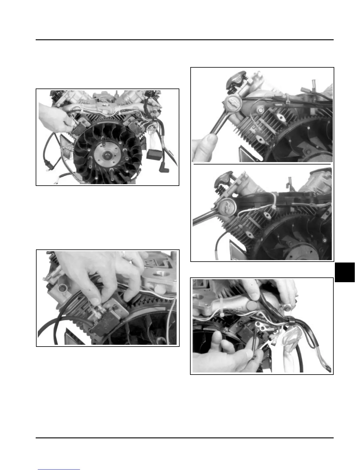
Figure 9-41. Disconnecting Leads from Ignition
Modules.
2. Rotate the flywheel so the magnet is away from
the modules.
3. Remove the mounting screws and ignition
modules. Note the position of ignition modules.
Figure 9-42. Position of SMART-SPARK
™
Ignition
Module.
Remove Intake Manifold
1. Remove the four hex. flange screws securing the
intake manifold to the cylinder heads. Note which
screws hold the wiring clamps.
2. Remove the intake manifold and the intake
manifold gaskets (aluminum intake manifolds) or
O-Rings (plastic intake manifolds). See Figure
9-43.
Figure 9-43. Removing Intake Manifold.
Figure 9-44. Bolt Wiring Harness Detail.
Aluminum
Intake
Manifold
Plastic Intake
Manifold
Remove Ignition Modules
1. Disconnect the lead(s)* from each ignition
module. See Figure 9-41. *Modules for non-
SMART-SPARK
™
ignition systems have only one
kill lead.
3. Leave the wiring harness attached to the
manifold.