8.30
Section 8
Electrical System and Components
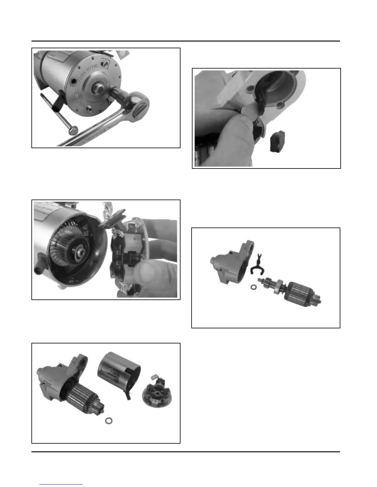
Figure 8-44. Removing Thru Bolts.
5. Remove the commutator end plate assembly,
containing the brush holder, brushes, springs, and
locking caps. Remove the thrust washer from
inside the commutator end. See Figure 8-45.
Figure 8-45. Removing Commutator End Plate
Assembly.
6. Remove the frame from the armature and drive
end cap. See Figure 8-46.
Figure 8-48. Armature and Lever Removed.
10. Push the stop collar down to expose the retaining
ring. See Figure 8-49.
Figure 8-46. Starter Frame Removed.
7. Remove the drive lever pivot bushing and backing
plate from the end cap. See Figure 8-47.
Figure 8-47.
8. Take out the drive lever and pull the armature out
of the drive end cap. See Figure 8-48.
9. Remove the thrust washer from the armature
shaft. See Figure 8-48.