8.9
Section 8
Electrical System and Components
8
Electrical Systems Wiring Diagrams and
Battery Charging Systems
This engine is equipped with a regulated battery
charging system.
Refer to the following wiring diagram and
troubleshooting guide to test and service this system.
NOTE: Observe the following guidelines to prevent
damage to the electrical system and
components.
1. Make sure the battery polarity is correct. A
negative (-) ground system is used.
2. Disconnect the rectifier-regulator leads and/or
wiring harness plug before doing electric
welding on the equipment powered by the
engine. Also disconnect other electrical
accessories in common ground with the engine.
3. Prevent the stator (AC) leads from touching or
shorting while the engine is running. This could
damage the stator.
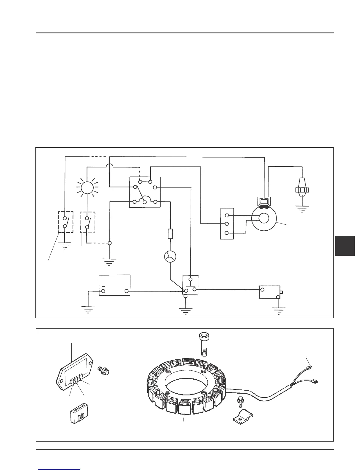
Electric Start Engines, 15/20 amp Battery Charging System
Ground-to-Kill Lead (White)
(Violet)
(Blue)
(Red)
S
B
R
A
M
GND
Keyswitch
Optional
Oil Sentry
Switch
(Indicator
Light)
Optional
Oil Sentry
Switch
(Shutdown)
Battery
Solenoid Starter
Optional
Fuse
Optional
Ammeter
B+
Rectifier
Regulator
AC
AC
Ignition
Module
Spark
Plug
Flywheel
Stator
+
Figure 8-8. Wiring Diagram - Electric Start Engines, 15/20 amp Battery Charging System.
Figure 8-9. 15/20 amp Stator and Rectifier-Regulator.
Rectifier-Regulator
AC
B+
AC
15 Amp Stator
AC Leads
 Loading...


