8.15
Section 8
Electrical System and Components
8
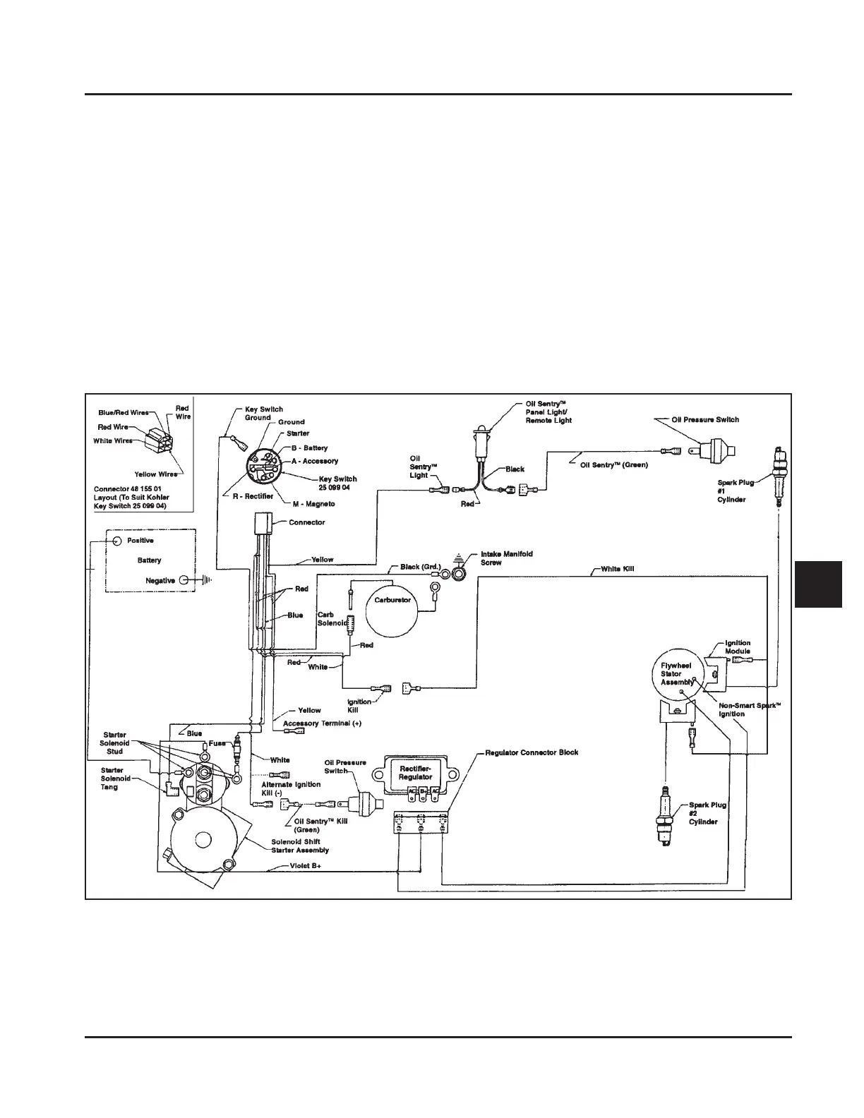
15/20/25 Amp Regulated Charging System
Figure 8-17. Wiring Diagram - 15/20/25 Amp Regulated Battery Charging System with Fixed Timing.
Battery Charging System
General
Most engines are equipped with a 15 or 20 amp
regulated charging system. Some have a 25 amp
regulated charging system. See Figure 8-17 and 8-18
for the 15/20/25 amp charging system diagram. Some
engines utilize a 3 amp unregulated system with
optional 70 watt lighting circuit. Refer to Figure 8-22.
NOTE: Observe the following guidelines to avoid
damage to the electrical system and
components:
• Make sure the battery polarity is correct. A
negative (-) ground system is used.
• Disconnect the rectifier-regulator plug and/or the
wiring harness plug before doing any electric
welding on the equipment powered by the
engine. Also, disconnect all other electrical
accessories in common ground with the engine.
• Prevent the stator (AC) leads from touching or
shorting while the engine is running. This could
damage the stator.