5B.14
Section 5B
EFI Fuel System
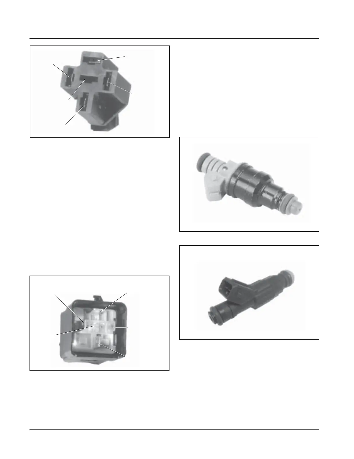
Figure 5B-17. Style 2 Fuel Injector.
General
The fuel injectors mount into the intake manifold, and
the fuel rail attaches to them at the top end.
Replaceable O-Rings on both ends of the injector
prevent external fuel leakage, and also insulate it from
heat and vibration. A special clip connects each
injector to the fuel rail, retaining it in place.
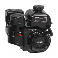
Figure 5B-15. Relay Terminal Details.
5. Connect an ohmmeter (Rx1 scale) between the
#85 and #86 terminals in the relay. There should
be continuity. See Figure 5B-15.
Figure 5B-14. Relay Connector.
a. Clean the connection and check wiring if
circuit was not completed.
3. Set meter for DC voltage. Touch red tester lead to
the #30 terminal in relay connector. A reading of
12 volts should be indicated at all times.
4. Connect red lead of meter to the #85 terminal in
relay connector. Turn key switch to the “on”
position. Battery voltage should be present.
a. No voltage present indicates a problem in the
wiring or at the connector.
b. If voltage is present, the wiring to the
connector is good. Turn ignition switch ‘‘off’’
and proceed to test 5 to test the relay.
6. Attach ohmmeter leads to the #30 and #87
terminals in relay. Initially, there should be no
continuity. Using a 12 volt power supply, connect
the positive (+) lead to the #85 terminal, and touch
the negative (-) lead to the #86 terminal. When 12
volts is applied, the relay should activate and
continuity should exist (circuit made) between
the #30 and #87 terminals. Repeat the test several
times. If, at any time the relay fails to activate the
circuit, replace the relay.
Fuel Injectors
Terminal #87 -
Feed To Ignition
Coils, Fuel
Injectors, and
Fuel Pump
Terminal #86 -
ECU
Controlled
Ground
Terminal #87A -
Not used
Terminal #85 -
Ignition Switch
Voltage
Terminal #30 -
Permanent Battery Voltage
Terminal #85 -
Ignition
Switch Voltage
Terminal #87 - Feed
to Ignition Coils,
Fuel Injectors,
and Fuel Pump
Terminal #86 -
ECU Controlled
Ground
Terminal #30 -
Permanent
Battery Voltage
Terminal
#87A -
Not Used
Figure 5B-16. Style 1 Fuel Injector.