68
Disassembly/Inspection and Service
KohlerEngines.com 24 690 06 Rev. C
Oil Pump Assembly
Oil pump is mounted inside of closure plate. If service
is required, refer to Disassembly, Inspection, and
Reassembly procedures.
Disassembly
1. Remove screws.
2. Remove oil pump assembly from closure plate.
3. Remove oil pump rotor.
4. Remove oil pickup by unhooking locking clip, and
pulling it free from oil pump body.
5. If relief valve is similar to shown, drive out pin to
remove oil pressure relief valve piston and spring.
Refer to following inspection and reassembly
procedures.
If relief valve is a one-piece style, staked to oil pump
housing removal should not be attempted, nor is
internal servicing possible. If a problem with relief
valve is encountered, oil pump should be replaced.
Inspection
Inspect oil pump housing, gear, and rotors for nicks,
burrs, wear, or any visible damage. If any parts are worn
or damaged, replace oil pump.
Inspect oil pressure relief valve piston. It should be free
of nicks or burrs.
Check spring for wear or distortion. Free length of spring
should be approximately 47.4 mm (1.8 in.). Replace
spring if it is distorted or worn.
Reassembly
1. Install pressure relief valve piston and spring.
2. Install oil pickup to oil pump body. Lubricate O-ring
with oil and make sure it remains in groove as
pickup is being installed.
3. Install rotor.
4. Install oil pump body to closure plate and secure
with screws. Torque screws as follows:
a. Install fastener into screw location 1 and lightly
tighten to position pump.
b. Install fastener into screw location 2 and fully
torque to recommended value.
c. Torque fastener in screw location 1 to
recommended value.
First Time Installation: 10.7 N·m (95 in. lb.)
All Reinstallations: 6.7 N·m (60 in. lb.)
5. After torquing, rotate gear and check for freedom of
movement. Make sure there is no binding. If binding
occurs, loosen screws, reposition pump, retorque
screws and recheck movement.
Remove Camshaft
Remove camshaft and shim.
Inspection and Service
Check lobes of camshaft for wear or damage. See
Specifi cations for minimum lift tolerance. Inspect
cam gear for badly worn, chipped or missing teeth.
Replacement of camshaft will be necessary if any of
these conditions exist.
Remove Connecting Rods with Pistons and Rings
NOTE: If a carbon ridge is present at top of either
cylinder bore, use a ridge reamer tool to remove
ridge before attempting to remove piston.
NOTE: Cylinders are numbered on crankcase. Use
numbers to mark each end cap, connecting rod
and piston for reassembly. Do not mix end caps
and connecting rods.
1. Remove screws securing closest connecting rod end
cap. Remove end cap.
2. Carefully remove connecting rod and piston
assembly from cylinder bore.
3. Repeat above procedures for other connecting rod
and piston assembly.
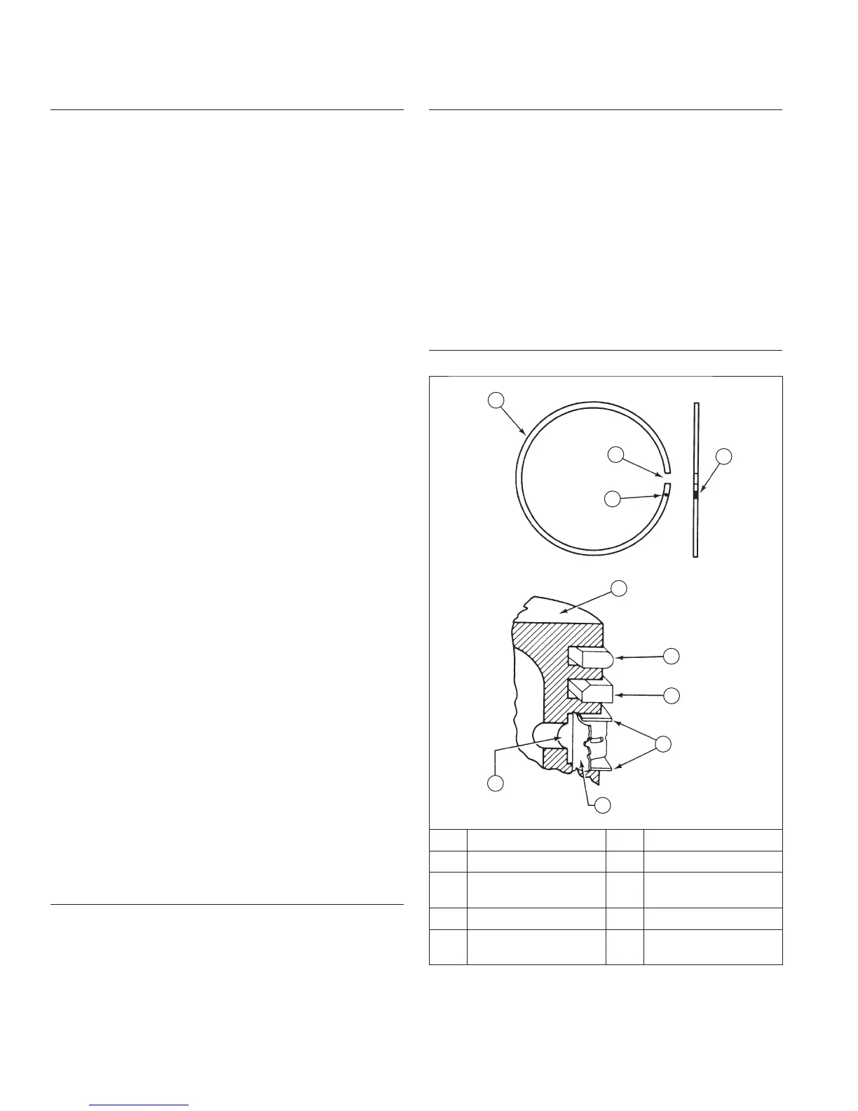
Piston and Rings
Piston and Rings Components and Details
A
B
C
D
E
F
J
G
I
H
A Piston Ring B End Gap
C Identifi cation Mark D Piston
E
Top Compression
Ring
F
Center Compression
Ring
G Rails H Expander
I
Oil Control Ring
(3 Piece)
J Dye Colored Stripe