9.10
Section 9
Disassembly
1. Check if the extra retaining clips are present.
If so, cut the clips, so they can be removed
and discard. Mark the tops of the knobs where
they were located. Order 3 new clips, Part No.
24 018 03-S, for installation during reassembly.
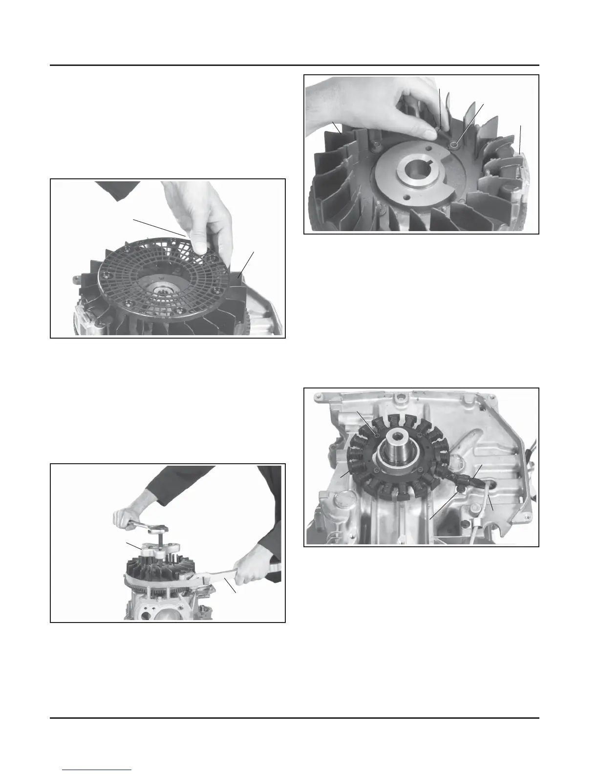
2. Remove the screen by unsnapping it from the
fan. See Figure 9-32.
Figure 9-35. Removing Stator.
Remove Oil Pan
1. Invert the engine, so the PTO end of crankshaft is
up.
2. Remove the twelve hex. fl ange screws securing
the oil pan to the crankcase. See Figure 9-36.
Figure 9-32. Removing Plastic Grass Screen.
3. Remove the fl ywheel from the crankshaft using a
puller. See Figure 9-33.
NOTE: Always use a puller to remove the
fl ywheel from the crankshaft. Do not
strike the crankshaft or fl ywheel, as
these parts could become cracked or
damaged.
Flywheel Puller
Strap Wrench
Figure 9-34. Removing Fan from Flywheel.
Remove the Stator and Wiring Harness
1. Remove the stator leads from connector body.
2. Remove the hex. fl ange screw and clip securing
the stator leads to the crankcase. See
Figure 9-35.
3. Remove the hex. fl ange screw and clip securing
the kill lead to the crankcase. Remove the four
hex. socket head screws and stator.
Hex. Socket
Screws (4)
Stator
Hex. Flange
Screw and Clip
Stator Leads
Kill Lead
Fan
Hex. Flange Screws (4)
Flywheel
Spacers (4)
Unsnap Grass
Screen from Fan
Fan
Figure 9-33. Removing Flywheel with a Puller.
4. Remove the four hex. fl ange screws, spacers,
and fan from fl ywheel. See Figure 9-34. Later
engines will have shoulder screws and no
spacers.