10.12
Section 10
Inspection and Reconditioning
Figure 10-13. Governor Shaft.
2. Install new governor regulating pin, Part No.
12 380 01-S, and governor gear assembly Part
No. 12 043 05-S.
3. Make sure governor gear assembly rotates freely.
Procedure to Install Governor Shaft:
1. Install new pin by pressing or lightly tapping into
crankcase. It must be installed so that it protrudes
1.289 plus or minus .004 in. above the crankcase
boss. See Figure 10-13.
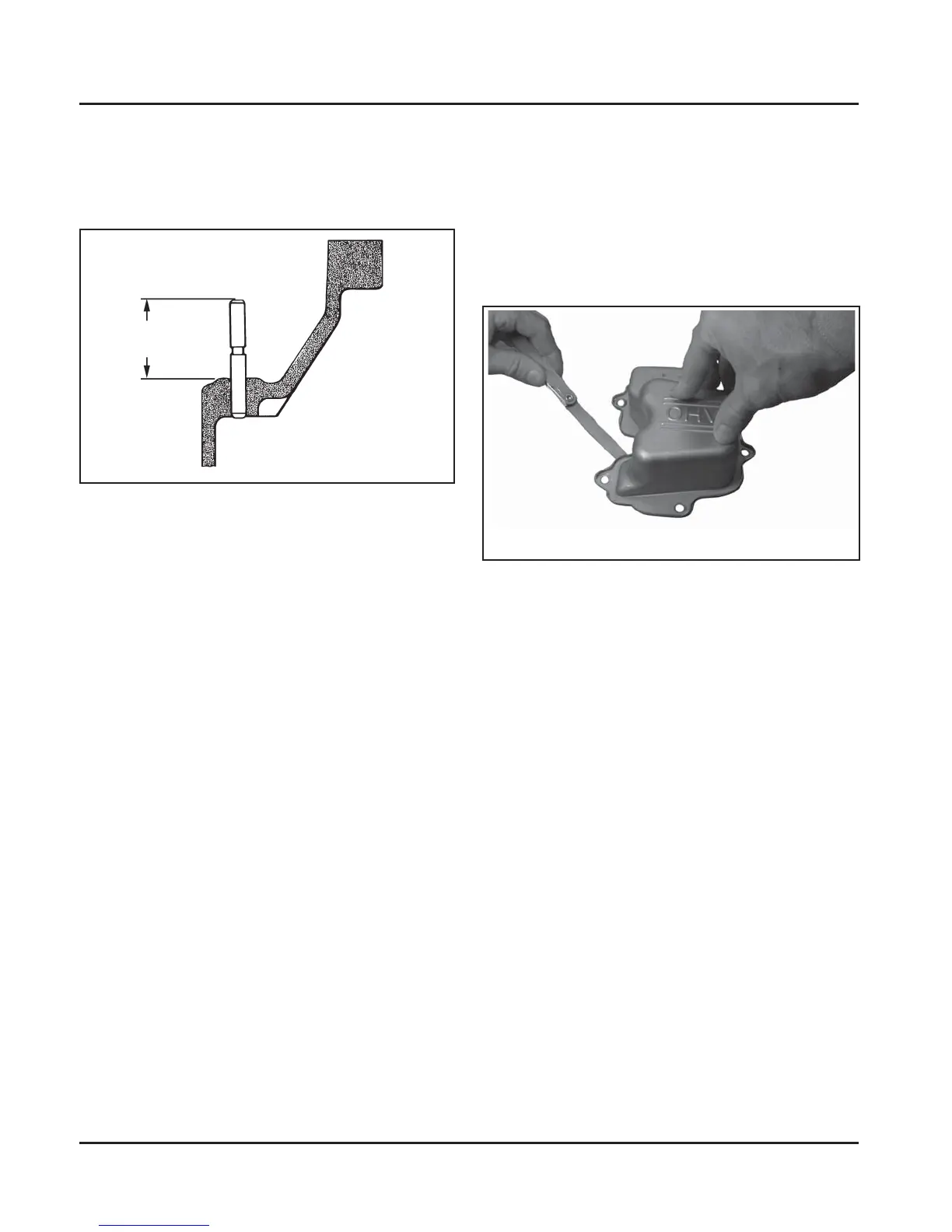
Stamped Steel Valve Cover
If the engine has stamped steel valve cover, the
sealing surface must be checked for fl atness
prior to reinstallation. Hold the valve cover down
fi rmly against a fl at, level surface or piece of glass,
and check around the entire perimeter that a .012 in.
(.30 mm) feeler gauge cannot be inserted anywhere.
See Figures 10-14. If the gauge goes in anywhere, the
cover needs to be replaced.
± .004
1.289
Figure 10-14. Checking with Feeler Gauge.