Install Ignition Modules
1. Rotate ywheel to position magnet away from
ignition module bosses.
2. On engines equipped with SMART-SPARK
™,
both
modules are installed similarly with tabs out.
On engines not equipped with SMART-SPARK
™
modules are installed with spark plug lead wire from
module always away from cylinder. On cylinder 1,
single kill tab should be towards you. On cylinder 2,
single kill tab should be away from you (in).
3. Install each ignition module to crankcase bosses
with screws (hex ange or allen head, based on
model). Slide modules up as far away from ywheel
as possible and snug screws to hold them in that
position.
4. Rotate ywheel to position magnet directly under
one ignition module.
5. Insert a 0.30 mm (0.012 in.) at feeler gauge
between magnet and ignition module. Loosen
screws enough to allow magnet to pull module
against feeler gauge.
6. Torque screws to 4.0-6.2 N·m (35-55 in. lb.).
7. Repeat steps 4 through 6 for other ignition module.
8. Rotate ywheel back and forth checking for
clearance between magnet and ignition modules.
Make sure magnet does not strike modules. Check
gap with a feeler gauge and readjust if necessary.
Final air gap: 0.280/0.330 mm (0.011/0.013 in.).
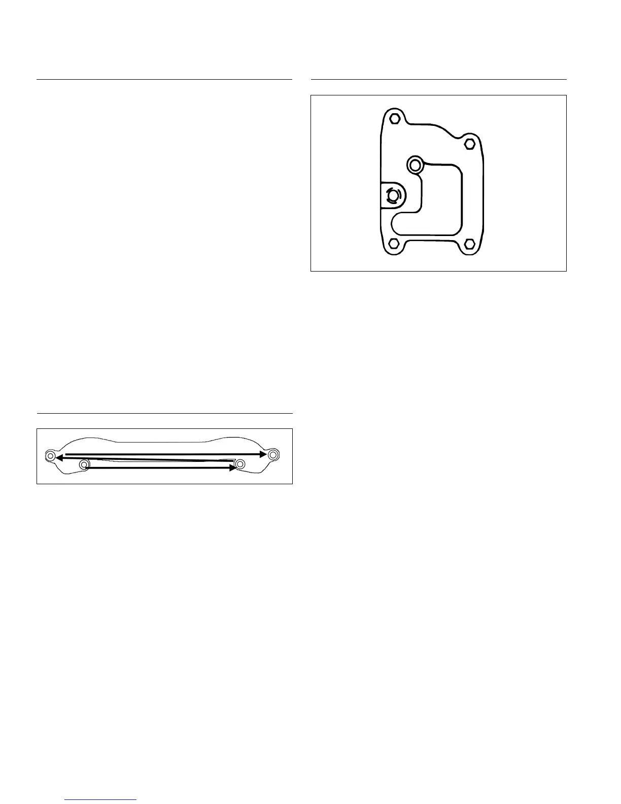
Install Intake Manifold
Torque Sequence
3
1 2
4
NOTE: If wires were disconnected from ignition modules
on engines with SMART-SPARK
™
, reattach
leads and seal base of terminal connectors with
GE/Novaguard G661 or equivalent dielectric
compound. Beads should overlap between
terminals to form a solid bridge of compound. Do
not put any compound inside terminals.
24 584 15-S ignition modules have a separator
barrier between terminals. On these modules,
seal base of terminals, but it is not necessary to
have overlapping beads of sealant between
connections.
1. Install intake manifold and new gaskets or O-rings
(plastic manifold), with wiring harness attached, to
cylinder heads. Slide any wiring harness clips onto
appropriate bolts before installing. Make sure
gaskets are in proper orientation. Using sequence
shown, torque screws in two increments, rst to
7.4 N·m (66 in. lb.), then to 9.9 N·m (88 in. lb.).
2. Connect kill lead to tab terminal on standard ignition
modules.
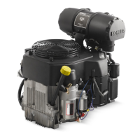
Install Breather Cover and Inner Bafes
Breather Cover Torque Sequence
1
2
3
4
RTV sealant was used on early models between
breather cover and crankcase. A gasket with imprinted
sealant beads is now used and recommended. Install as
follows.
1. Be sure sealing surfaces of crankcase and breather
cover are clean of old gasket material or RTV
sealant. Do not scrape surfaces as this could result
in leakage.
2. Check to make sure there are no nicks or burrs on
sealing surfaces.
3. Position breather gasket and cover on crankcase.
Install rst screws in locations 3 and 4 as shown.
Finger tighten at this time.
4. Install inner bafes using remaining screws and
nger tighten. Do not torque screws at this time; they
will be tightened after blower housing and outer
bafes are installed.
Reassembly
82
24 690 07 Rev. HKohlerEngines.com