Install Blower Housing and Outer Bafes
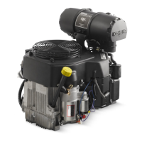
Wires on Starter Side of Engine
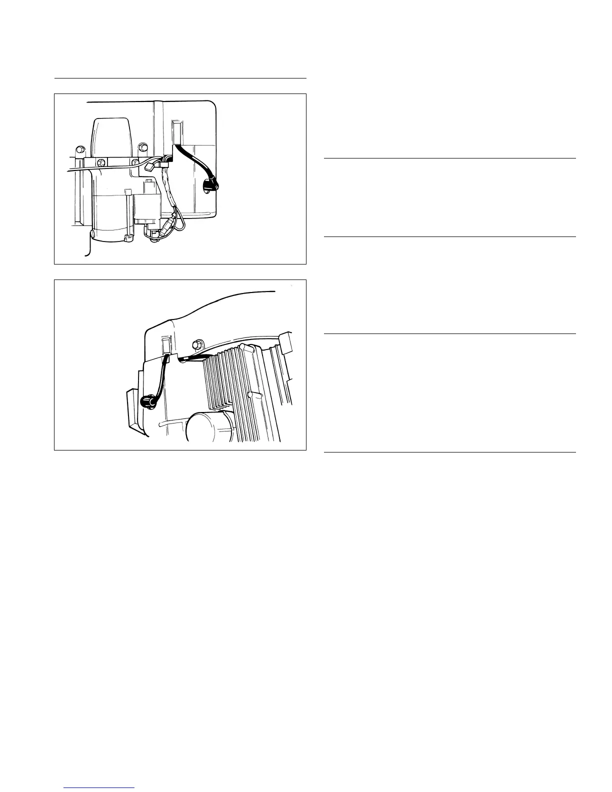
Wires on Oil Filter Side of Engine
NOTE: Do not completely tighten screws until all items
are installed to allow shifting for hole alignment.
1. Pull wire harness and spark plug leads out through
appropriate openings in shrouding.
2. Slide blower housing into position over front edge of
inner bafes. Start a few of screws to hold it in place.
3. Position outer bafes and secure using screws (two
long, two short) in front mounting holes (into cylinder
head), including any lifting strap or attached
bracket(s). Install two short screws in upper
mounting holes of outer bafes (into backing plates).
Use short screw on left side to mount wire harness
bracket. Be sure any leads are routed out through
proper offsets or notches, so they will not be pinched
between blower housing and bafes.
4. Tighten all shrouding fasteners. Torque blower
housing screws to 6.2 N·m (55 in. lb.) in a new hole,
or to 4.0 N·m (35 in. lb.) in a used hole. Torque
shorter M5 side bafe screws to 4.0 N·m (35 in. lb.).
Torque M5 side bafe screws (into cylinder head) to
6.2 N·m (55 in. lb.) in a new hole, or to 4.0 N·m
(35 in. lb.) in a used hole. Torque two lower M6
bafe mounting screws to 10.7 N·m (95 in. lb.) in a
new hole, or to 7.3 N·m (65 in. lb.) in a used hole.
5. If engine had a plastic debris screen that overlaps
blower housing, reinstall it now. Torque mounting
screws to 4.0 N·m (36 in. lb.). For a metal screen,
apply Loctite
®
242
®
to screw threads and torque
screws to 9.9 N·m (88 in. lb.).
6. Torque four breather cover screws to 7.3 N·m
(65 in. lb.) in sequence shown.
Install Oil Sentry
™
(if equipped)
1. Apply pipe sealant with Teon
®
(Loctite
®
PST
®
592™
Thread Sealant or equivalent) to threads of Oil
Sentry
™
switch and install it into breather cover.
Torque to 4.5 N·m (40 in. lb.).
2. Connect wire lead (green) to Oil Sentry
™
terminal.
Install Control Panel (if equipped)
1. Install panel to blower housing.
2. Connect throttle control shaft to throttle control
bracket.
3. Connect choke control cable to throttle control
bracket.
4. Connect Oil Sentry
™
indicator light wires.
Reconnect Rectier-Regulator
1. Install rectier-regulator in blower housing if
removed previously, then connect rectier-regulator
ground lead with washer and silver screw through
eyelet. If a grounding bracket is used, secure with
mounting screw and washer, against outer side of
rectier-regulator.
2. Install B+ terminal/lead into center position of
rectier-regulator plug and connect plug to rectier-
regulator.
SMART-SPARK
™
Module
On engines with SMART-SPARK
™
, reinstall SAM module
to blower housing or cylinder bafe. Do not over-tighten
retaining screws.
Reassembly
8324 690 07 Rev. H KohlerEngines.com