10.2
Section 10
Reassembly
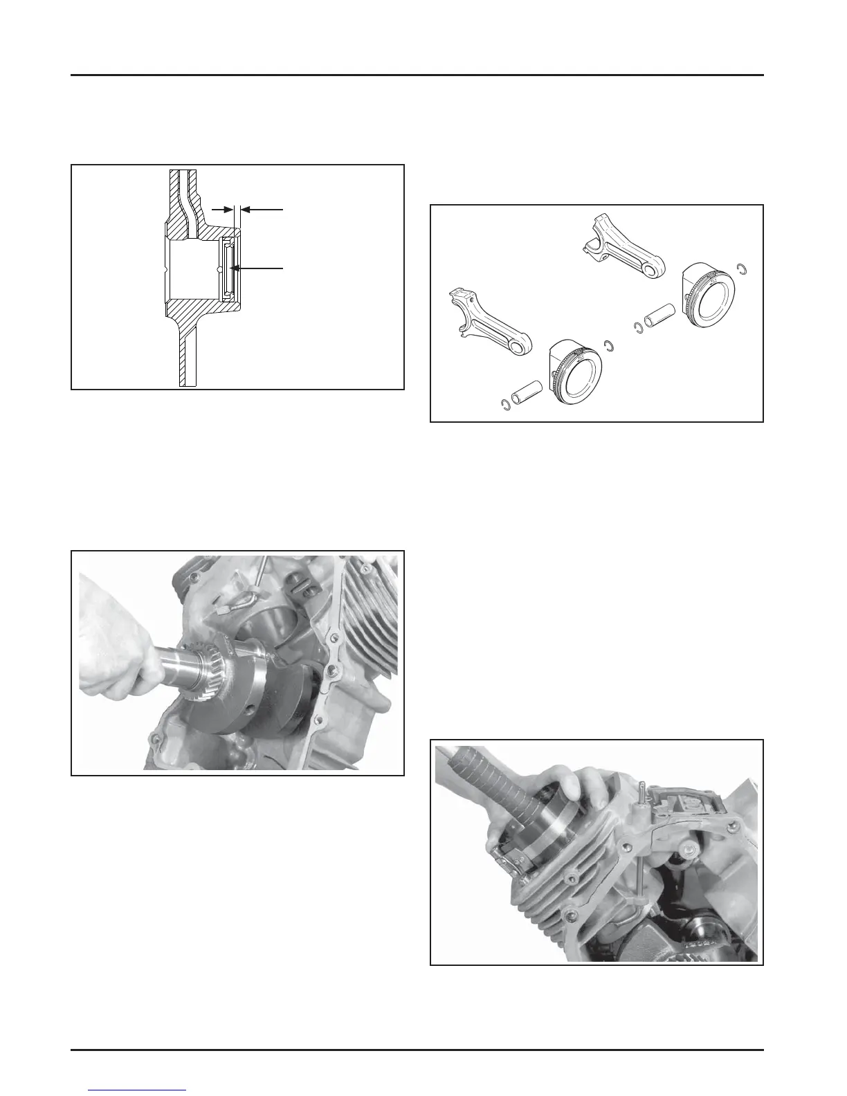
Cylinder #1
Cylinder #2
3. Drive the oil seal into the crankcase using a seal
driver. Make sure the oil seal is installed straight
and true in the bore to the depth shown in Figure
10-2.
NOTE: Proper orientation of the piston/connecting
rod assemblies inside the engine is extremely
important. Improper orientation can cause
extensive wear or damage. Be certain the
pistons and connecting rods are assembled
exactly as shown in Figure 10-4.
Figure 10-3. Installing Crankshaft.
Install Connecting Rods with Pistons and
Rings
NOTE: The cylinders are numbered on the crankcase.
Make sure to install the piston, connecting
rod and end cap into its appropriate cylinder
bore as previously marked at disassembly.
Do not mix the end caps and connecting
rods.
Figure 10-5. Installing Piston Assembly Using Ring
Compressor Tool.
Figure 10-2. Installing Oil Seal.
Install Crankshaft
1. Lubricate the cranksha journals and connecting
rod bearing surfaces with engine oil.
2. Carefully slide the fl ywheel end of the cranksha
through the main bearing in the crankcase. See
Figure 10-3.
Figure 10-4. Piston, Connecting Rod, and Pin
Detail.
1. Stagger the piston rings in the grooves until the
end gaps are 120° apart. The oil ring rails should
also be staggered.
2. Lubricate the cylinder bore, piston, and piston
rings with engine oil. Compress the rings of the
#1 piston using a piston ring compressor.
3. Make sure the FLY stamping on the piston is
facing towards the fl ywheel side of the engine.
Use a hammer with a rubber grip and gently
tap the piston into the cylinder as shown in
Figure 10-5. Be careful that the oil ring rails do
not spring free between the bo om of the ring
compressor and top of the cylinder.
4.5 mm
(.177) in.
Oil Seal

 Loading...