10
10.19
Section 10
Reassembly
Figure 10-67. Installing Starter and ECU Bracket.
2. Torque the two hex fl ange screws to 16.0 N·m
(142 in. lb.).
3. Connect the leads to the solenoid.
Install Electronic Control Unit (ECU)
1. Install ECU to the ECU bracket using the two hex
fl ange screws. Torque the M5 screws to 6.2 N·m
(55 in. lb.) into new holes or 4.0 N·m (35 in. lb.)
into used holes. See Figure 10-68.
2. Connect the Black and Grey electrical connectors.
The connectors and ECU are keyed in such a way
so they cannot be installed incorrectly.
Figure 10-68. Torque ECU screws.
NOTE: The ECU pins should be coated with a thin
layer of electrical grease to prevent fre ing
and corrosion and may need to be reapplied
if the ECU is being reused.
Install Throttle Body
1. Install a new thro le body O-ring prior to
installation. Make sure all holes align and are
open.
2. Install the thro le body, thro le position sensor,
intake air temperature sensor, thro le linkage,
spring and bushing, as an assembly. See Figure
10-69.
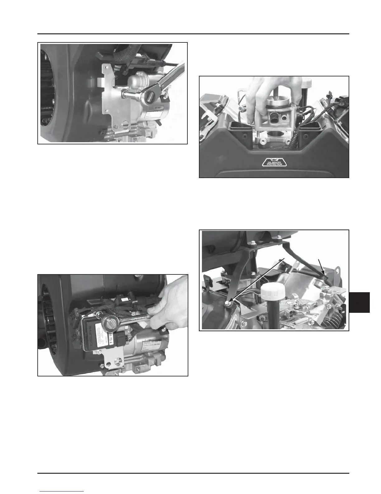
Torque Bracket Screws
Figure 10-69. Installing Throttle Body Assembly.
3. Install the air cleaner bracket (models with
heavy-duty air cleaner only) to the valve covers.
Torque the screws to 9.9 N·m (88 in. lb.). See
Figure 10-70.
Figure 10-70. Install Air Cleaner Bracket.
4. Push the electrical connector onto the intake
air temperature sensor making sure a good
connection is made by listening for a click. See
Figure 10-71.
5. Connect the breather hose to the thro le body
using a pliers to compress the spring clamp.
Route the hose around the thro le body and
connect to the breather cover using a spring
clamp. See Figure 10-71.

 Loading...