9.12
Section 9
Inspection and Reconditioning
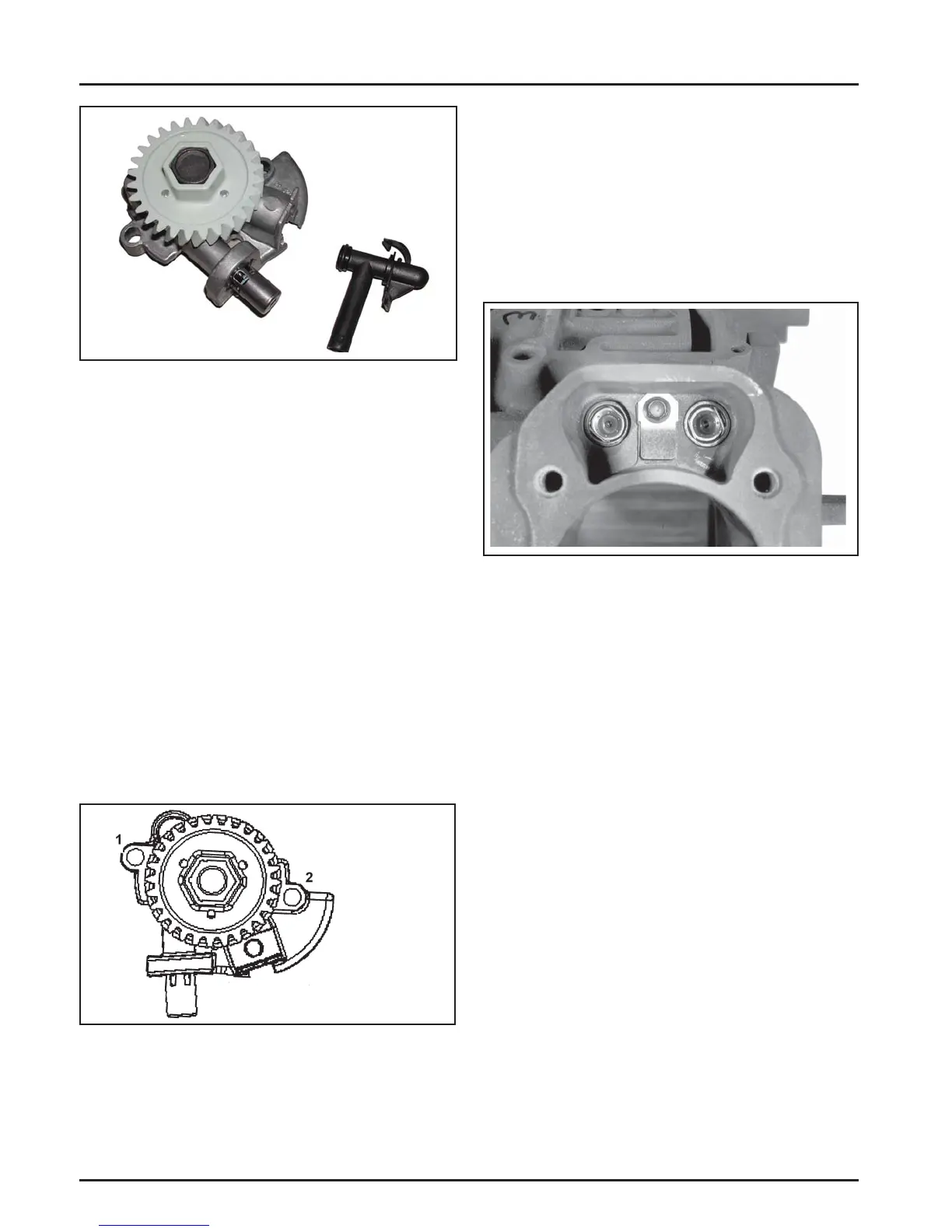
Figure 9-16. Oil Pump, Plastic Oil Pickup, and
One-Piece Relief Valve.
Reassembly
1. Install the oil pickup to the oil pump body.
Lubricate the O-ring with oil and make sure it
remains in the groove as the pickup is being
installed.
2. Install the rotor.
3. Install the oil pump body to the oil pan and
secure with the two hex fl ange screws. Torque
the hex fl ange screws as follows:
a. Install fastener into location No. 1 and lightly
tighten to position pump.
b. Install fastener into location No. 2 and fully
torque to the recommended value.
c. Torque fastener in location No. 1 to the
recommended value.
First Time Installation: 10.7 N·m (95 in. lb.)
All Reinstallations: 6.7 N·m (60 in. lb.)
4. A er torquing, rotate the gear and check for
freedom of movement. Make sure there is no
binding. If binding occurs, loosen the screws,
reposition the pump, retorque the hex fl ange
screws and recheck the movement.
Crankcase Breather System
The breather system is designed to control the amount
of oil in the head area and still maintain the necessary
vacuum in the crankcase.
Oil Pump Torque Sequence
Figure 9-17. Crankcase with Breather Reed.
A spring steel reed and stop is mounted on each bank
of the crankcase, between the li er bores. See Figure
9-17. When the pistons move downward, air is pushed
past the reeds into the cylinder head cavities. On the
#2 cylinder, the upper end of the head is completely
sealed by the rocker cover, so a low, positive pressure
is created in the head cavity. The #1 rocker cover
has a hole in it for venting. The bo om nipple of
an oil separator canister is fi ed into the hole with
a grommet. From the top nipple of the canister, a
breather hose goes back to the air cleaner base. The air
moving into the #1 head cavity is fi ltered through the
oil separator and then is drawn into the air intake. See
Figure 9-18.
The upward travel of the pistons closes the reeds and
creates a low vacuum in the lower crankcase. The
combination of low pressure above and low vacuum
below forces any accumulated oil out of the #2 head
area into the crankcase. On the #1 bank you have
atmospheric pressure above and vacuum below, again
drawing any oil toward the crankcase.
 Loading...


