10.5
Section 10
Reassembly
10
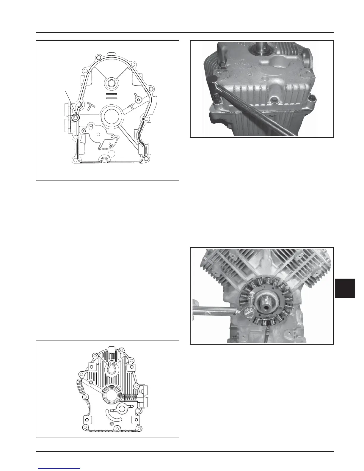
Figure 10-13. Oil Pan Sealant Pattern.
4. Make sure the end of the governor cross sha is
lying against the bo om of cylinder 1 inside the
crankcase. See Figure 10-10.
5. Install the oil pan to the crankcase. Carefully seat
the camsha and the cranksha into their mating
bearings. Rotate the cranksha slightly to help
engage the oil pump and governor gear meshes.
6. Install the ten hex fl ange screws securing the oil
pan to the crankcase. Torque the fasteners in the
sequence shown in Figure 10-14 to 25.6 N·m
(227 in. lb.). One of the ten mounting screws has
a thread sealant patch. This screw is typically
installed in the number 10 hole shown in Figure
10-14. Reapply pipe sealant with Tefl on
®
(Loctite
®
592
™
PST
®
Thread Sealant or equivalent) to the
number 10 oil pan screw as required. See Figure
10-15.
Figure 10-15. Torquing Oil Pan Fasteners.
Install Stator and Backing Plate
1. Apply pipe sealant with Tefl on
®
(Loctite
®
592
™
PST
®
Thread Sealant or equivalent) to the stator
mounting holes.
2. Position the stator aligning the mounting holes so
that the leads are at the bo om, towards the
crankcase.
3. Install and torque the two hex fl ange screws to
6.2 N·m (55 in. lb.) for new holes or 4.0 N·m
(35 in. lb.) for used holes. See Figure 10-16.
Apply 1.5 mm (1/16 in.)
bead of sealant.
RTV must be
all around
O-ring
groove
Point B
Fill groove between points A and B with RTV.
Point A
1
10
8
6
4
2
9
7
5
3
Figure 10-16. Torquing Stator Screws.
4. Route the stator leads in the crankcase channel,
then install the backing plate. Secure with the
four hex fl ange screws. See Figures 10-17 and
10-18. Torque the screws 10.7 N·m (95 in. lb.) for
new holes or 7.3 N·m (65 in. lb.) for used holes.
Figure 10-14. Oil Pan Fastener Torque Sequence.
 Loading...


