TP-7070 8/20 77Section 4 Accessories
1
2
3
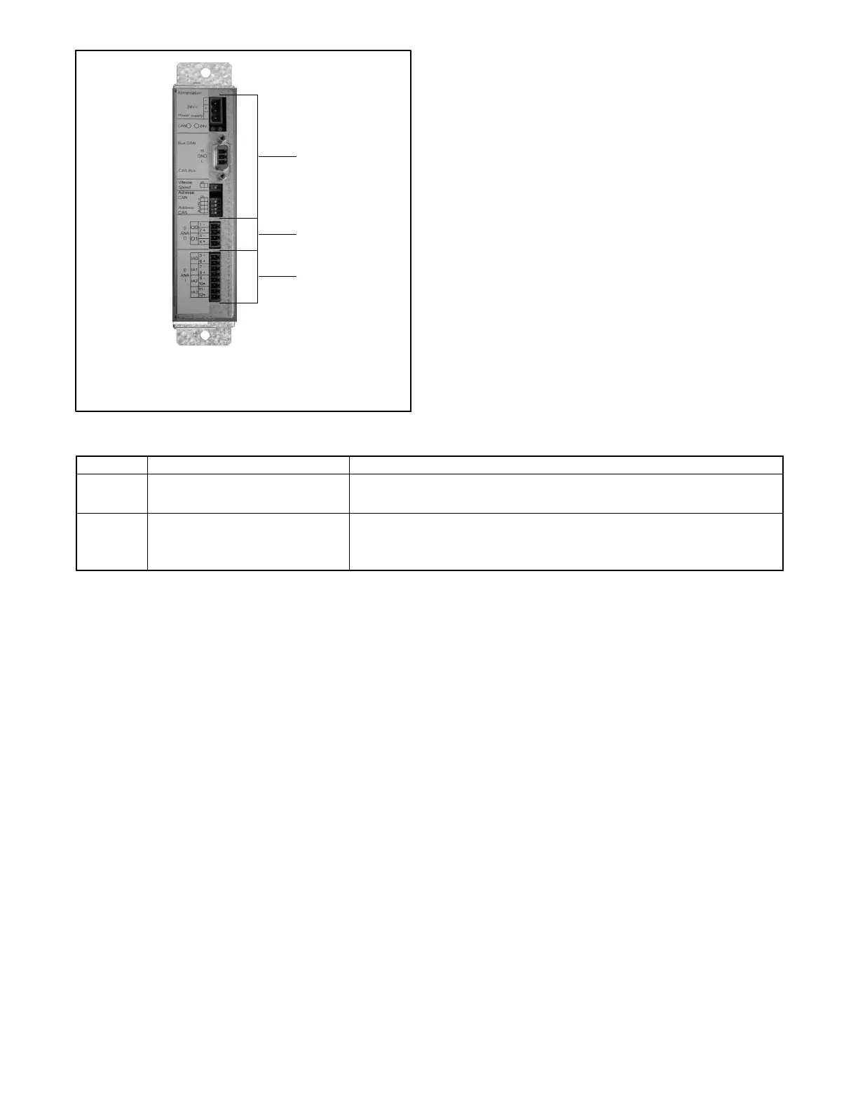
31613391201/301/401
1. Factory connections or settings
2. Analog output connections 0 and 1
3. Analog input connections 0 - 3
Figure 4-5 Analog Input/Output Module
LED Description LED Operation
1 Power LED Green: The module is correctly powered.
Off: Module is not powered.
2 Can bus 1 Communication LED Flashing green: CAN communication is consistent.
Steady green: No CAN communication.
Off: No CAN communication.
Figure 4-6 Module Diagnostic LEDs
 Loading...