9
131
_07
Fig. 9.5
E
Z
U
V
T
Fig. 9.6
W
E
J
AB
K
Fig. 9.7
F
AD
E
AC
AN
AE
Fig. 9.8
AM
AN
AG
AH
AL
E
AL
AN
ED0053029590
ASSEMBLY INFORMATION
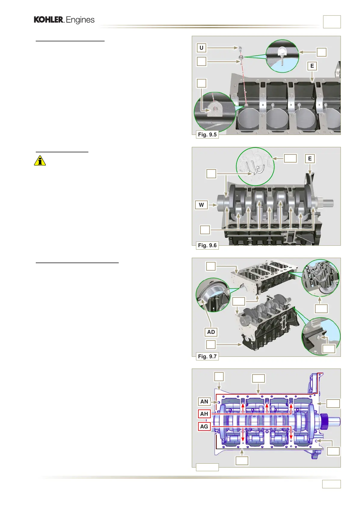
9.3.4 Oil spray nozzles
1 - Insert the sprayers V onto the upper crankcase E manually
screwing the screw fittings U.
2 -
Direct the sprayers V as shown Z and tighten the connecting
screws U (tightening torque of 10 Nm).
9.3.5 Crankshaft
Important
• Carry out the checks described in Par. 8.4.1 and Par. 8.4.2.
1 -
Check that the crankshaft half-bearings are mounted
correctly on the upper crankcase E.
2 - Lubricate the main journal and crankpin J, with oil.
3 - Insert the crankshaft W into its seat on the upper crankcase
E.
4 - Insert the 2 shoulder half-rings K, between the crankshaft
W and the upper crankcase E (AB detail).
4 -
Spread a bead of Loctite 5660 (rif. AL) of approx 1 mm
thickness on the surface AM of the upper crankshaft half C
being careful not to block the oil feed grooves AG and the
return oil sump AH.
5 - Join the two crankshaft halves E and F observing the guide
pins AN.
9.3.6 Lower semi-crankcase
1 -Check that the crankshaft half-bearings are mounted
correctly on the lower crankcase F (AC detail).
2 - Assemble the 2 shoulder half-rings AD onto
the lower crankcase F applying two drops of grease to
keep them in their seat.
3 - Check that the coupling surfaces AE are free from dirt and
grit.

 Loading...


