18
1
_07
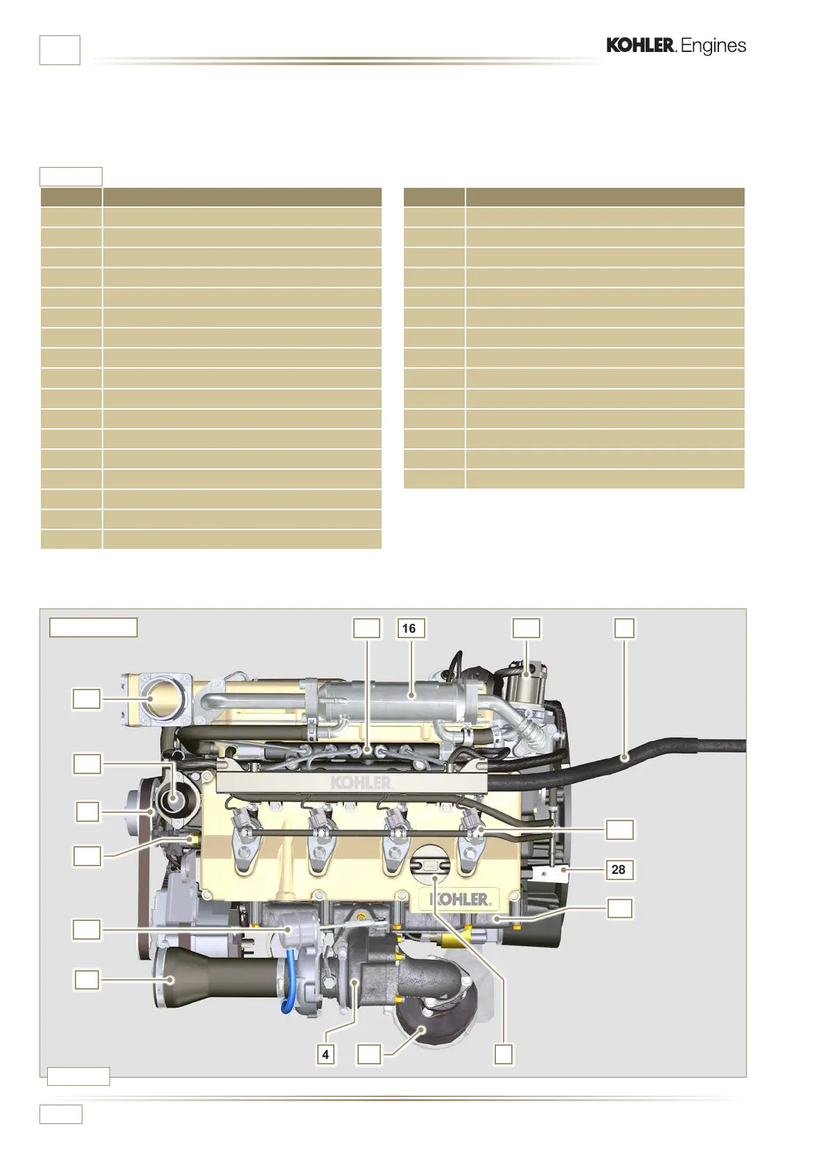
Fig. 1.10
29
28
27
14
11
12
25
16
30
4 115
22
2
26
31
ED0053029590
GENERAL INFORMATION
POS. DESCRIPTION
1 Oil filler cap
2 Wiring
3 ECU
4 Turbocharger
5 Oil pressure switch
6 Starter motor
7 Oil steam separator
8 Oil drain plug
9 Engine identication name plate
10 Alternator
11 Coolant pump
12 Coolant temperature sensor
13 Oil filler cap side
14 Thermostatic valve
15 Catalyst
16 EGR Cooler
17 High-pressure fuel injection pump
Tab. 1.3
This paragraph illustrates all external components that are
present in the base conguration of the engine.
For components present on engines that differ from those
represented in these illustrations, refer to Chap. 11.
NOTE: The illustrated components may differ from those
illustrated; the illustration is only as an example.
POS. DESCRIPTION
18 Oil Cooler
19 Lub. oil lter
20 Oil dipstick
21 Fuel lter
22 EGR valve
23 Crankshaft pulley (2
nd
PTO)
24 Flywheel (1
st
PTO)
25 Intake manifold
26 Waste Gate valve control actuator
27 Exhaust manifold
28 Flange bell
29 Electronic injectors
30 Common Rail
31 Air intake hose
UPPER VIEW

 Loading...


