42
2
_07
H
M
Q
R
L
N
Fig. 2.30
ED0053029590
TECHNICAL INFORMATION
POS. DESCRIPTION
1 Air in intake from air lter
2 Air in compression
3 Air in intercooler ow
4 Air cooling
5 Air in intake manifold ow
6 Air in head intake
7 Air in cylinder intake
8 Gas in cylinder outlet
9 Gas in head outlet
10 Gas in outlet towards catalyst
11 Gas in oxidation
12 Gas in recycle towards EGR valve
13 Gas in EGR valve outlet
14 Gas cooling (in EGR Cooler)
15 Exhaust gas recirculation into intake manifold
A Intake manifold
B Exhaust manifold
C Upper crankcase
D Lower crankcase
E Oil sump
F Catalyst
G Radiator/intercooler
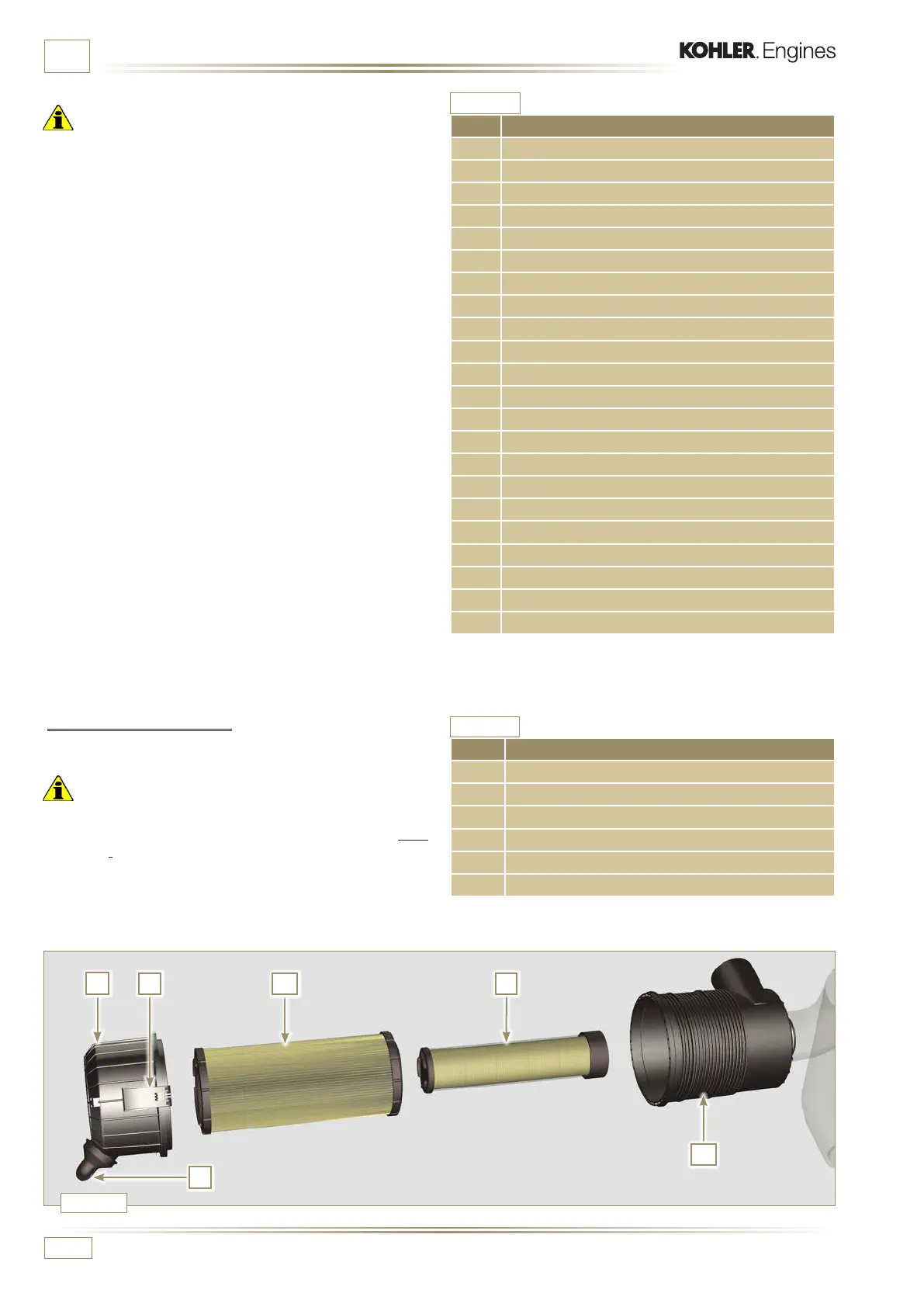
POS. DESCRIPTION
H Air lter cartridge
L Air lter safety cartridge
M Filter cover
N Filter support
Q Dust exhaust valve
R Filter cover hook
2.12.4 Air lter (optional)
NOTE: Component not necessarily supplied by KOHLER.
Important
• The air filter is a dry type of filter with a paper filtering element;
elements H and L are replaceable (refer to Tab. 2.8 and
Tab. 2.9 for procedure frequency on components).
• The filter intake must be positioned in a cool area.
• Should a hose be used, the length must not exceed 400 mm
and is to be as straight as possible.
Tab. 2.32
Tab. 2.31
Important
• The diagrams in Fig. 2.28 and Fig. 2.29 do not have an air
filter, which must always be present and connected by means
of an intake hose to the turbocharger.
• The air temperature inside the intake manifold must never
exceed that of the environment by 10°C.
F i l t e r e d a i r i s s u c k e d b y t h e t u r b o c h a r g e r, w h i c h c o m p r e s s e s a n d
sends it to the intercooler (as a consequence of compression,
the air increases the temperature - the Intercooler cools it -
this process enables better performance during combustion
inside the cylinders). From the Intercooler, it is sent to the
intake manifold and, via ducts in the cylinder head, enters
t h e c y l i n d e r s . C o m p r e s s e d a i r i n s i d e t h e c y l i n d e r s a n d m i x e d
with the fuel transforms into Gas after combustion. The
gas is expelled from the cylinders and sent to the exhaust
m an i f o l d . T h e ex h a u s t m a n i f o l d s e n d s t h e G a s e s t o 2 d u c t s :
- 1 s t d u c t : t o t h e t u r b o c h a r g e r b o d y ( t h e e x p e l l e d G a s e s
activate the turbine), the Gases then proceed towards
t h e c a t a l y s t , w h i c h b r e a k d o w n t h e p o l l u t a n t s c o n t a i n e d
in them before being denitely expelled.
- 2nd duct: to the EGR circuit, which takes care of
recovering a part of the Gases that return to intake
(this process burns less oxygen when power is not
requested, thus breaking down pollutants further).
The EGR circuit is managed by ECU, which controls the EGR
valve that provides for the recovery of Gases when the engine
does not require power.
The EGR circuit is furnished with a heat exchanger (EGR
C o o l e r ) , w h i c h c o o l s t h e r e c o v e r e d G a s e s ( t h i s p r o c e s s e n a b l e s
better performance during combustion inside the cylinders).

 Loading...


