EasyManua.ls Logo

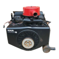
Kohler MAGNUM M18

Kohler MAGNUM M18
139 pages
To Next Page IconTo Next Page
To Previous Page IconTo Previous Page
Loading...
SECTION
10
INSPECTION
AND
RECONDITIONING
Valve
Guides
If
a
valve
guide
is
wom
beyond
specifications,
it
will
not
guide
the
valve
in
a
straight
line.
This
may
result
in
burnt
valve
faces
or
seats,
loss
of
compression,
and
excessive
oil
consumption.
To
check
valve
guide
to
valve
stem
clearance,
thor-
oughly
clean
the
valve
guide
and,
using
a
split-ball
gauge,
measure
the
inside
diameter.
Then,
using
an
outside
micrometer,
measure
the
diameter
of
the
valve
stem
at
several
points
on
the
stem
where
it
moves
in
the
valve
guide.
Use
the
largest
stem
diameter
to
cal-
culate
the
clearance.
If
the
clearance
exceeds
.005”
on
intake
or
.007”
on
exhaust
valve,
determine
wheth-
er
the
valve
stem
or
the
guide
Is
responsible
for
the
excessive
clearance.
If
the
valve
stem
diameter
is
within
specifications,
then
replace
the
valve
guide.
Remove
Valve
Gulde
The
valve
guides
are
a
tight
press
fit
in
the
cylinder
barrel.
A
valve
guide
removal
tool
is
recommended
to
remove
the
guides
(refer
to
Section
2,
"Special
Tools").
To
remove
valve
guide,
refer
to
Figure
10-6
and
proceed
as
follows:
Adapter
Cylinder
Stud--5/16"
x
2-1/2"
Figure
10-6.
Pulling
Valve
Guide.
.
Install
5/16-18
NC
nut
on
coarse
threaded
end
of
2-1/2"
long
stud.
2.
Insert
other
end
of
stud
through
valve
guide
bore
and
install
5/16-24
NF
nut.
Tighten
both
nuts
securely.
NOTE:
Valve
guide
must
be
held
firmly
by
the
stud
assembly
so
that
all
slide
hammer
force
will
act
on
the
guide.
3.
Assemble
the
valve
guide
removal
adapter
to
the
stud
and
then
the
slide
hammer
to
the
adapter.
4.
Use
the
slide
hammer
to
pull
the
guide
out.
Install
Valve
Guide
To
install
valve
guide,
proceed
as
follows:
1.
Make
sure
valve
guide
bore
is
clean
and
free
of
nicks
or
bums.
2.
Using
valve
guide
driver
(Refer
to
Section
2,
"Special
Tools"),
align
and
then
press
guide
in
until
valve
guide
driver
bottoms
on
depth
gauge.
See
Figure
10-7.
Driver
(Tool
#11763)
Depth
Gauge
(Tool
#11770-tor
M18
A
#11771-for
M20)
Cylinder
Barrel
Figure
10-7.
Installing
Valve
Guide.
3.
Valve
guides
are
often
slightly
cornpressed
during
insertion.
Use
a
piloted
reamer
(Refer
to
Section
2,
“Special
Tools”)
and
then
a
finishing
reamer
to
resize
the
guide
bore
to
.3125".
Refer
to
Figure
10-8.
10.7

Related product manuals