EasyManua.ls Logo

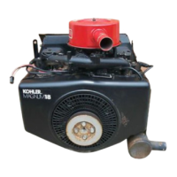
Kohler MAGNUM M18

Kohler MAGNUM M18
139 pages
To Next Page IconTo Next Page
To Previous Page IconTo Previous Page
Loading...
SECTION
11
REASSEMBLY
a
к
Insert
Flat
Feeler
Gauge
к
Between
Valve
Stem
And
Tappet
pose
SN
W
Intake
Valve
г
Exhaust
Valve
Cylinder
Barrel
Valve
Spring
ARES
Valve
Springs
Compressor
à
Keepers
Figure
11-32.
Measuring
Valve-to-Tappet
Clearance.
Clearance
Specifications
-
Intake
Valve
(Closest
to
Flywheel)
-003”/.006”
Exhaust
Valve
(Seat
Angle)
(Closest
to
PTO)
45°
-016"/.019"
30?*
.011"/014"
*Serlal
No.
1816500646
and
later.
3.
Rotate
the
crankshaft
360°
and
measure
the
valve-to-tappet
clearance
for
the
remaining
cylinder.
4,
If
the
clearance
is
insufficient,
grind
the
valve
stems
until
the
correct
clearance
is
obtained.
Make
sure
the
valve
stems
are
ground
perfectly
flat
and
smoath.
If
the
clearance
is
excessive,
replace
the
valves
and
recheck
clearance.
INSTALL
VALVES
1.
Install
the
intake
valve
seals
to
valve
guides.
2.
Install
the
valve
springs
(close
coils
towards
cylin-
der
head
surface),
exhaust
valve
rotators,
lower
intake
valve
spring
retainers,
and
valves.
3.
Compress
the
springs
using
a
valve
spring
com-
pressor
and
install
keepers.
Refer
to
Figure
11-33.
11.12
Figure
11-33.
Installing
Valves.
Side
#2
Shown.
INSTALL
CYLINDER
HEADS
AND
SPARK
PLUGS
1.
Install
gaskets,
cylinder
heads,
plain
washers,
and
hex.
cap
screws
(lubricate
threads
with
oil).
Torque
hex.
cap
screws
in
increments
in
the
se-
quence
shown
in
Figure
11-34
to
15/20
ft.
Ib.
Figure
11-34.
Cylinder
Head
Fastener
Torque
Sequence.
2.
Install
the
spark plugs
(0.035"
gap);
torque
to
10/15
ft.
Ib.

Related product manuals