EasyManua.ls Logo

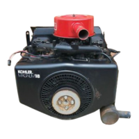
Kohler MAGNUM M18

Kohler MAGNUM M18
139 pages
To Next Page IconTo Next Page
To Previous Page IconTo Previous Page
Loading...
SECTION
8
ELECTRICAL
SYSTEM
AND
COMPONENTS
4.
Measure
the
resistance
of
the
coil
in
the
solenoid
using
an
ohmmeter.
Connect
one
meter
lead
to
the
case
ground
and
one
lead
to
the
tab
terminal.
If
the
resistance
is
5.2/6.3
ohms,
the
coil
is
OK.
ELECTRIC
STARTER
If
the
resistance
is
low
or
0
chms,
the
coil
is
shorted.
Replace
solenoid.
if
the
resistance
is
infinity
ohms,
the
coil
is
open.
Replace
solenoid.
Commutator
End
Cap
Brushes
And
Springs
Starter
Frame
(Includes
Permanent
Magnets)
Au
Ы
Thru
Bolts
Drive
End
Cap
Starter
Drive
Components
oo
Starter
Assembly
Drive
Shaft
Splines
Drive
Pinion
Dust
Cover
ч
Ѕрасег
d.
Anti-drift
a
Spring
E
g
X
А
Y
Stop
Gear
Spacer
«0
Stop
Nut
Dust
Cover
Ü
Figure
8-17.
Bendix
Drive
Electric
Starter.
BENDIX
DRIVE
ELECTRIC
STARTER
The
M18
&
M20
engines
will
use
either
a
Bendix
drive
starter
as
shown
in
Figure
8-17
or
a
solenoid
shift
type
starter
described
on
pages
8.16
through
8.21.
Operation
-
(Bendix
Drive
Type
Starter)
When
power
is
applied
to
the
starter,
the
armature
ro-
tates.
As
the
armature
rotates,
the
drive
pinion
moves
out
on
the
splined
drive
shaft
into
mesh
with
the
fly-
wheel
ring
gear.
When
the
pinion
reaches
the
end
of
the
drive
shatt,
it
rotates
the
flywheel
cranking
the
engine.
When
the
engine
starts,
the
flywheel
rotates
faster
than
the
armature
and
drive
pinion.
This
moves
the
drive
pinion
out
of
mesh
with
the
ring
gear
and
into
the
retracted
position.
When
power
is
removed
from
the
starter,
the
armature
stops
rotating
and
the
pinion
is
held
in
the
retracted
position
by
the
anti-drift
spring.
NOTE:
Do
not
crank
the
engine
continuously
for
more
than
10
seconds
at
a
time.
If
the
engine
does
not
start,
allow
a
60
second
cool-down
period
between
starting
attempts.
Failure
to
follow
these
guidelines
can
bum
out
the
starter
motor.

Related product manuals