EasyManua.ls Logo

Kohler STERLING 5400 Series User Manual

Kohler STERLING 5400 Series
6 pages
To Next Page IconTo Next Page
Page #1 background imageLoading...
Page #1 background image
Leg
1/32" (1 mm)
Cut Line
"B" Mark
B
Top Track
B
#8-18 x 1-1/2"
Screw Cover
Screw Cover
x2
x2
3
2
1
Notch
Rails
Long Leg
Outside of
the Shower
Wall Jamb – Top View
x2
Hanger
Bracket
Gasket
x2
Tin Snips
9/64"
Miter Box
32-teeth Per Inch Blade
Masking Tape
100% Silicone Sealant
Rubber Mallet
5/16" Masonry Bit for Tile
5/16"
1218520**
Hardware Skin Pack
1219162
End Cap
Screw
1048208-C
Wall Jamb*
Gasket
1213732
Barrel Nut
1050048-A
#8-32 x 3/8"
8-32 x 1/4"
Screw
1051142-A
Roller
1050047
Hanger Bracket
1219763-01**
Bolt
1077763-A
Left Door
Panel*
Wall Jamb*
Serial Number Label
1077762
Anchor
1218971
Bumper
1031943**
Screw Cover
1214505-01**
Top Track
1056868-A
Screw
1218476**
Center Guide
#8-18 x 1-1/2"
1213333-01**
Bottom Track
Handle
Right Door
Panel*
Spacer
Post
Back Plate
Screw
Bottom Wall
Jamb Notch
Bottom Wall
Jamb Notch
Handle Kit
1285596-01*
A
A
"A" Mark
Cut Line
1/4" (6 mm)
Measure distance “A.” Subtract 1/4” (6 mm) or
the width of a number 2 pencil from “A” and cut
the bottom track.
Position the bottom track on the center of the
ledge. If needed, file the ends to match the
corners.
Center the bottom track on the ledge with the leg
to the outside. Tape the bottom track in place and
mark the position.
IMPORTANT! The bottom track and wall jamb
must sit flat against the shower ledge and the
wall. If needed, trim and file the wall jamb. Use a
coin to match and to transfer the corner radius of
the shower to the wall jamb.
Position the wall jambs over the bottom track.
The long leg of each wall jamb faces the outside
of the shower. Plumb both wall jambs. Mark the
screw holes.
Remove the wall jambs. Drill 5/16” holes into the
walls and insert the anchors.
Reposition both wall jambs. Secure the wall
jambs with screws.
Measure distance “B” above the wall jambs.
Subtract 1/32” (1 mm) or the width of a saw
blade from “B.” Mark and cut the top track.
Place the top track over the wall jambs (either
side may face out). At each end of the top track,
insert and twist a bumper into place over the
rails. Slide the bumpers against the wall jambs.
For both doors, slide a gasket over the top of the
glass panel and into each mounting hole. Press
the hanger bracket over the gasket and align the
hanger brackets with the mounting holes.
5400 Heavy Glass Series Sliding Shower Doors
Sliding Shower DoorsSliding Bath Doors
11218556-2-G
USA/Canada: 1-800-STERLING (1-800-783-7546)
México: 001-877-680-1310
1218556-2-G
Installation and Care Instructions
*Need help? Contact the STERLING Customer Care Center at
1-800-STERLING (1-800-783-7546).
For service parts information, care and cleaning, and other information,
visit www.sterlingplumbing.com
**Finish/color code must be specifi ed when ordering.
Retain this document for future servicing.
Record model number from box for reference.
Model Number:______________
Required Tools Parts Identifi cation
2 3 4
7 86 9
1 5
10
WARNING: Risk of serious injury. Damage prior to installation can
result in glass shattering. Inspect the glass and all parts for damage
before installation.
WARNING: Risk of serious injury. Improper installation can result
in glass shattering. Follow all installation instructions.
WARNING: Risk of serious injury. Do not cut tempered glass.
Tempered glass will shatter if cut.
WARNING: Risk of serious injury. Shower door and side panels
can shatter. Regularly inspect the glass and all parts for damage,
missing, or loose parts.
WARNING: Risk of serious injury. Always wear safety glasses
while cutting and drilling.
SterlingPlumbing.com
Critical Information!
Read Before Installation!
Read and follow all instructions.
IMPORTANT! Do not touch the edges of the tempered glass with tools or
any other hard objects. Do not set the unframed tempered glass directly on
the floor or any hard surface.
IMPORTANT! Leave this manual for the end user.
Read these instructions before installing or using this product.
IMPORTANT! Do not cut the top track the same length as the bottom track.
NOTICE: The warranty does not apply to a product that has been modified
or altered in a manner other than as expressly permitted in the Installation
and Care Guide.
Walls must be within 3/8” (10 mm) of plumb.
Cover the drain with tape to avoid loss of small parts.
Follow the silicone sealant manufacturer’s instructions for application and
curing time.
To watch this installation video online, visit www.sterlingplumbing.com.
For care and cleaning and other information; visit
www.sterlingplumbing.com/care-and-cleaning.

Other manuals for Kohler STERLING 5400 Series

Question and Answer IconNeed help?

Do you have a question about the Kohler STERLING 5400 Series and is the answer not in the manual?

Kohler STERLING 5400 Series Specifications

General IconGeneral
BrandKohler
ModelSTERLING 5400 Series
CategoryBathroom Fixtures
LanguageEnglish

Summary

Critical Information and Warnings

Safety Warnings

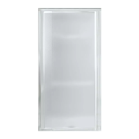
Includes risks of injury from glass shattering due to damage or improper installation.

Tempered Glass Handling

Advises against cutting tempered glass and handling glass edges with hard objects.

Important Installation Notes

Provides guidance on not touching glass edges, leaving the manual for users, and track cutting.

Warranty Disclaimer

States warranty does not apply to modified products.

Tools and Parts

Required Tools

Lists tools necessary for the installation process.

Parts Identification

Details and labels all components included in the hardware skin pack.

Installation Guide

Step 1: Cut Bottom Track

Measure and cut the bottom track to the specified length.

Step 2: Position Bottom Track

Place the bottom track onto the ledge, filing ends if needed.

Step 3: Secure Bottom Track

Center the bottom track, tape it, and mark its position.

Step 4: Position Wall Jambs

Place wall jambs over the bottom track, ensuring plumbness and correct orientation.

Step 5: Mark Wall Jamb Holes

Mark screw hole positions on the wall for the wall jambs.

Step 6: Install Wall Anchors

Drill holes and insert anchors into the walls for mounting the wall jambs.

Step 7: Secure Wall Jambs

Reposition wall jambs and secure them with screws.

Step 8: Cut Top Track

Measure and cut the top track to the correct length.

Step 9: Position Top Track

Place the top track over the wall jambs.

Step 10: Install Bumpers

Insert bumpers into the top track and slide them against wall jambs.

Step 11: Secure Hanger Brackets

Thread bolts into barrel nuts to secure hanger brackets to door panels.

Step 12: Identify Inside Panel

Determine which door panel is the inside panel for correct placement.

Step 13: Install Rollers on Inside Panel

Assemble rollers onto the middle holes of hanger brackets for the inside panel.

Step 14: Mount Inside Panel

Lift and place the inside door panel onto the inside track.

Step 15: Install Rollers on Outside Panel

Assemble rollers onto the middle holes of hanger brackets for the outside panel.

Step 16: Mount Outside Panel

Lift and place the outside door panel onto the outside track.

Step 17: Position Door Guide

Place the guide under the lip of the bottom track and slide it into door frames.

Step 18: Adjust Door Rollers

Slide doors, adjusting rollers as needed for smooth operation.

Step 19: Secure Door Guide

Secure the guide in place using self-tapping screws.

Step 20: Glass Adjustment

Raise and lower the glass panels for final alignment.

Step 21: Assemble Handles

Assemble and install the door handles onto both panels.

Step 22: Seal Exterior Surfaces

Apply silicone sealant along the exterior of wall jambs and bottom track.

Step 23: Seal Interior Surfaces

Apply silicone sealant along interior wall jambs and where they meet the bottom track.

Troubleshooting and Warranty

Troubleshooting Door Alignment

Addresses issues like tilted panels or doors not touching bumpers.

Troubleshooting Water Leaks

Provides solutions for leaks between panels, jambs, or under the track.

Troubleshooting Door Operation

Offers advice for panels that are difficult to move.

Product Warranty Information

Details the limited warranty period and claim procedures.

Related product manuals