1
© 2017 Kolpin Outdoors Inc. REV 00
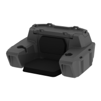
ATV Trunk & Lounger
Product Instructions | Part No: 4457
Kolpin Outdoors, Inc. | 9955 59th Ave N | Plymouth, MN 55442
(877) 956-5746 or (763) 478-5800 | kolpin.com | customerservice@kolpin.com
Item Qty Part Description Spare P/N
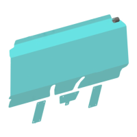
1 1 4457 Base -
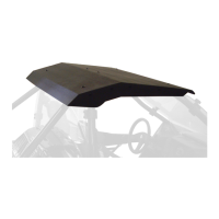
2 1 4457 Lid -
3 1 Upper Seat Pad K100163
4 1 Lower Seat Pad K100162
5 8 M6 x 12mm Screw 75-0039
6 8 M6 Washer 76-0012
7 2 Rubber Strap K100157
8 4 1/4” - 20 U-Bolt
9 8 1/4” Sealing Washer
10 8 U-Bolt Plate
11 8 1/4” Lock Washer
12 8 1/4” - 20 Nut
60-4411
MOUNTING
KIT
13 8 Rubber Thread Caps
2
Before you begin, read these instructions and check to be sure all parts and tools are accounted for. Please retain
these instructions for future reference and part ordering information. Note: If any parts are missing, do not return to
the store. Call us to help, toll free at 1-877-956-5746.
1
3 5
6
4 5
6
7
9
Parts List:
10
11
12
Please Note: The Mounting Hardware supplied with this
product is designed to be used on tubular steel ATV
Racks. ATVs with non-tubular or composite plastic racks
will require the use of custom hardware provided by the
customer.
Tools Required:
Drill
5/16” Drill Bit
7/16” Deep Socket or Wrench
Marking Utensil
Mounting Instructions:
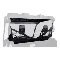
1.) Position the ATV Trunk & Lounger box onto the rear ATV rack in the desired position. Use your best judgement determining
where to locate the U-Bolts in order to provide a secure and stable installation. Its suggested to mount two of the U-Bolts onto
rack tubing that runs front to back and the other two U-Bolts on rack tubing that runs side to side. See Illustration 1-1.
2.) Mark or scribe the locations of the tubular rack where the four U-Bolts will be attached on the bottom of the box. The grid on
the bottom of the box can help identify location and assure centered and symmetrical alignment. The ATV rack can be removed
from the vehicle if necessary to allow better access to the bottom side of the rack. See Illustration 1-2.
3.) Remove the box and use the U-Bolt Plates [Item 10] as a template to mark the hole locations for each U-Bolt [Item 8]. Drill
eight 5/16” holes for the U-Bolts [Item 8] to pass through. See Illustration 1-3.
8
Ill. 1-2 Ill. 1-1 Ill. 1-3