The provided document is a Shop Manual for a Komatsu Wheel Loader, specifically the WA600-6 model, with serial numbers 60001 and up. This manual serves as a comprehensive guide for the maintenance, repair, and troubleshooting of the machine.
Function Description
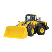
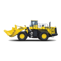
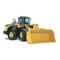
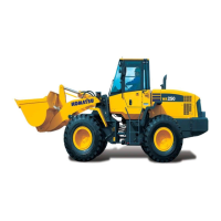
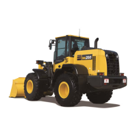
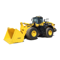
The Komatsu WA600-6 is a heavy-duty wheel loader designed for various material handling and earthmoving applications. As a wheel loader, its primary function is to scoop and transport loose materials such as sand, gravel, dirt, and other aggregates. It is equipped with a large front-mounted bucket, which is hydraulically operated to lift, tilt, and dump materials. The "WA" designation typically indicates a wheel loader, and the "600" suggests its size or capacity within Komatsu's product line, with "-6" indicating a specific generation or model revision. The machine is designed for robust performance in demanding environments, offering high productivity and operational efficiency.
Important Technical Specifications
The manual's index provides a detailed breakdown of the machine's components and systems, indicating the depth of technical information available. While specific numerical values for horsepower, bucket capacity, or operating weight are not directly visible on the provided pages, the structure of the manual suggests that these details are covered in the "01 Specification" section. Key technical areas covered include:
- Engine and Cooling System: Detailed information on the engine, cooling system, and transmission mount. This includes components like the cooling fan, cooling pump, and cooling motor.
- Power Train: Divided into multiple parts, covering the torque converter, modulation clutch, transmission, transfer, ECM (Engine Control Module), main relief valve, and differential, including limited slip differential. Serial numbers for the WA600-6 start from 60001, indicating a specific production range for which this manual is applicable.
- Steering System: Includes the steering piping diagram, steering column, joystick EPC lever, lock valve, steering valve, rotary valve, steering control valve, two-way restrictor valve, stop valve, steering pump, steering cylinder, emergency steering piping diagram, inverter valve, and emergency steering pump.
- Brake System: Covers the brake piping diagram, brake valve, accumulator charge valve, EPC relief valve, accumulator (for brake), slack adjuster, parking brake, parking brake solenoid valve, and emergency parking brake release valve, and brake cooling pump.
- Undercarriage and Frame: Details on the undercarriage and frame, center hinge pin.
- Hydraulic System: Divided into two parts, covering the hydraulic piping diagram, work equipment control lever linkage, hydraulic tank, work equipment hydraulic pump, control valve, ECSS (Electronic Control Suspension System), each function and operation of each valve, accumulator (for PPC circuit), and triple pump.
- Work Equipment: Includes work equipment linkage, bucket, bucket positioner and boom kick-out, work equipment lubrication, and work equipment cylinder.
- Cab and its Attachments: Covers ROPS cab, air conditioner.
- Electrical System: Divided into multiple parts, covering the machine monitor system, machine monitor, work equipment control system, transmission controller system, electric transmission control, engine starting/stopping circuit, parking brake circuit, sensor, VHMS controller related, and work equipment electric lever.
- Diagrams and Drawings: Includes hydraulic diagrams and drawings, and electrical diagrams and drawings.
The manual also includes "Standard value table" (Section 20) and "Testing and adjusting" (Section 30) which would contain critical operational parameters and tolerances for various components, such as engine speed, exhaust temperature, valve clearance, compression pressure, oil pressure, fuel pressure, and hydraulic pressure.
Usage Features
The WA600-6, as a wheel loader, is designed for ease of operation and high maneuverability in various job sites. The presence of a "Joystick EPC lever" and "ECSS (Electronic Control Suspension System)" suggests advanced control and operator comfort features. The "VHMS controller" (Vehicle Health Monitoring System) indicates sophisticated onboard diagnostics and monitoring capabilities, which enhance operational efficiency and predictive maintenance. The "ROPS cab" (Roll-Over Protective Structure) highlights a focus on operator safety. The "ecot3" logo on the cover is a Komatsu branding for environmentally friendly technologies, suggesting features like reduced emissions and improved fuel efficiency.
Maintenance Features
The Shop Manual is primarily a maintenance and repair tool, offering extensive features to support the upkeep of the WA600-6.
- Comprehensive Index and Foreword (00 Index and foreword): This section outlines the manual's structure, safety notices, and basic information on how to read the manual. It emphasizes the importance of following safety precautions, proper handling of electrical and hydraulic components, and correct procedures for connecting and disconnecting wiring harnesses and connectors.
- Safety Notices: Detailed safety instructions are provided, including warnings about working with heavy loads, handling wire ropes, precautions for overhead hoist cranes, and procedures for disconnecting and connecting hoses and tubes in the air conditioner circuit.
- Explanation of Terms for Maintenance Standard: Defines standard size and tolerance, standard interference, and repair limit and allowable value or allowable dimension, crucial for accurate repairs.
- Handling of Electric Equipment and Hydraulic Component: Specific guidelines for handling controllers, wiring harnesses, and hydraulic components to prevent damage and ensure proper function. This includes instructions on preventing dirt/dust ingress, proper connection/disconnection techniques, and precautions during arc welding.
- Precautions When Carrying Out Operation: General guidelines for removal and installation work, including proper disposal of coolant, covering disconnected hoses/tubes, draining oil, matching marks, handling wiring, using lifting equipment, and cleaning work areas.
- Precautions When Carrying Out the Operation: Detailed steps for refilling with coolant, oil, and grease, checking cylinder head and manifolds, checking muffler and exhaust pipe, and ensuring proper function of the cooling system.
- Method of Disassembling and Connecting Push-Pull Type Coupler: Specific instructions for handling different types of push-pull couplers (Type 1, Type 2, Type 3) to ensure proper disconnection and connection.
- Standard Tightening Torque Table: Comprehensive tables for bolts and nuts, split flange bolts, O-ring boss piping joints, hoses (taper seal type and face seal type), face seal joints, and eye joints, ensuring correct assembly and preventing damage.
- Conversion Table: Provides conversion factors for various units (millimeters to inches, kilogram to pound, liters to U.S. gallons, kg/cm² to lb/in², temperature conversions) to assist technicians working with different measurement systems.
- Color Codes Table: Lists color codes for wires and types of circuits, essential for electrical troubleshooting and wiring repairs.
- Troubleshooting (40 Troubleshooting): This section details how to identify failed parts and repair them, often categorized by failure modes and including error codes (e.g., "Failure code [1500L0] Transmission oil pressure plugging"). The extensive list of failure codes covers various systems like transmission, engine, alternator, hydraulic, electrical, and sensor-related issues, providing a structured approach to diagnostics.
- Disassembly and Assembly (50 Disassembly and assembly): Provides detailed procedures for removing, installing, disassembling, and assembling each component, including tightening torques, quantities, and weights of materials like coating material, oil, grease, and coolant. This section covers major components such as the engine, power train, brake system, undercarriage, hydraulic system, work equipment, cab, and electrical system.
The manual's structure and content are designed to empower technicians with the necessary information to perform thorough and accurate maintenance, ensuring the longevity and optimal performance of the Komatsu WA600-6 Wheel Loader.