This document serves as a Field Assembly Instruction manual for the Komatsu HM400-3 Articulated Dump Truck, specifically for serial numbers 3001 and up. It provides comprehensive guidance for the assembly, adjustment, and initial inspection of the machine, ensuring proper setup and functionality.
Function Description:
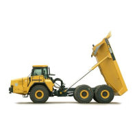
The Komatsu HM400-3 is an articulated dump truck designed for heavy-duty material transport in demanding environments. This manual details the procedures required to assemble the truck from its mobile shipping style to a fully operational state. Key assembly steps include positioning the bare machine, installing tires, mounting the body, and adjusting various components. The manual also covers the installation and adjustment of safety and operational features such as rear-view mirrors, guards, antennas, and the rear monitor system. Furthermore, it outlines the critical process of adjusting the nitrogen gas in the front and rear suspensions and connecting the hoist cylinder, which are essential for the truck's load-carrying and dumping capabilities. The final stage involves applying decals and a thorough field assembly inspection to verify all systems are functioning correctly and meet Komatsu's standards.
Important Technical Specifications:
The manual provides specifications for the HM400-3 completed truck and its removed units.
- HM400-3 Completed Truck (Self-propelled travel):
- Weight: 33,660 kg
- Overall length: 11,122 mm
- Overall width: 3,450 mm
- Overall height (when empty): 3,735 mm
- Removed Units:
- Bare machine: 33,600 kg, 11,122 mm (length), 3,450 mm (width), 3,735 mm (height)
- Exterior parts (2 pcs.): 3.2 kg
- Suspension Gas Adjustment:
- Front Suspension Cylinder:
- MIN (retracted fully): 40 ± 1 (dimension A)
- OIL (specified quantity): 101 ± 3
- EMPTY: 176 ± 10
- MAX (extracted fully): 217 ± 1
- Rear Suspension Cylinder:
- MIN (retracted fully): 36 ± 1 (dimension A)
- OIL (specified quantity): 76 ± 3
- EMPTY: 106 ± 5
- MAX (extracted fully): 126 ± 1
- Hoist Cylinder Tightening Torque: 157 – 196 Nm {16.0 – 20.0 kgm} for pin fixing bolt (3).
- Tire Inflation Pressure (When dump body is empty):
- Front wheels: 0.37 ± 0.01 MPa
- Front & Rear wheels: 0.39 ± 0.01 MPa
- Body Lifting Speed (Oil temperature: 80°C):
- Engine speed: Full speed (1,800rpm): 12.0 ± 1.5 sec
- Body Lowering Speed (Lever at FLOAT, Oil temperature: 70-90 °C):
- Engine speed: Power down: 9.0 ± 1.5 sec
- Hydraulic Drift of Dump Body: Must be 85 mm or less in 5 minutes (at 70% (50°) condition).
- Potentiometer Voltage:
- Dump lever LOWER end: 0.46 – 0.54V
- Dump lever RAISE end: 4.00 – 4.70V
Usage Features:
The manual emphasizes a systematic approach to assembly and adjustment, ensuring the truck is ready for safe and efficient operation.
- Rear View Mirror Unfolding and Adjustment: Detailed steps are provided for unfolding and fixing the rear-view mirrors, crucial for operator visibility.
- Antenna Installation: Instructions for installing both KOMTRAX and radio antennas, ensuring communication and telematics functionality.
- Rear Monitor System: A comprehensive procedure for installing and adjusting the rear monitor, including setting guide lines for tire outside width and body rear end. This feature enhances safety during reversing and maneuvering. The monitor can be configured to display the rear view continuously, even when the shift lever is not in "R," by turning off the "Reverse-interlock enabled mode."
- Suspension Adjustment: The process for adjusting the N2 gas in the front and rear suspensions is critical for maintaining optimal ride comfort, stability, and load distribution. This involves bleeding air, pouring nitrogen gas simultaneously into both cylinders, and checking the suspension cylinder length.
- Hoist Cylinder Connection: Detailed steps for connecting the hoist cylinder, including adjusting height with a crane and tightening fixing bolts, are provided to ensure proper dumping mechanism operation.
- Decal Sticking: Instructions for applying decals to the body, contributing to the machine's identification and branding.
Maintenance Features:
The manual incorporates several elements that contribute to the long-term maintenance and reliability of the HM400-3.
- Necessary Tools and Equipment: A comprehensive list of tools (e.g., ring wrenches, sockets, impact wrenches, torque wrenches, grease gun, suspension gas pouring tool) and equipment (e.g., crane, forklift, compressor, stepladder, steel plate, wood block, nylon sling, lifting tire, shackle) is provided for efficient and safe assembly and subsequent maintenance tasks.
- Inspection Procedures: The "Field Assembly Inspection Report" appendix outlines a detailed checklist for various components and functions, including:
- Engine oil and hydraulic oil levels.
- Functionality of horn, back-up buzzer, clearance lamp, headlamps, high beam, turn signal lamps, hazard lamp, backup lamps, and brake lamps.
- Fog lamp operation.
- Rear view monitor functionality.
- Engine and transmission inspections for oil and water leakage.
- Hydraulic oil system inspection (tank, cylinder, pump, piping).
- Potentiometer voltage check for the dump lever.
- Dump body shock and alignment checks.
- Body lifting and lowering speeds.
- Hydraulic drift of the dump body.
- Length of suspension cylinders.
- Safety pin function and storage.
- Tightness of tire hub nuts.
- Tire inflation pressure and flaw inspection.
- Hoist cylinder plated surfaces for rust or damage.
- Calibration of Dump Body System: A specific calibration procedure is outlined to ensure the dump body system and potentiometer are adjusted satisfactorily. This involves warming the hydraulic oil, cycling the dump lever through FLOAT and UP positions at both low and high engine idle speeds, and verifying smooth seating of the dump body.
- Precautions: Throughout the manual, precautions are highlighted for specific procedures, such as using protective plates when installing slings, bleeding air from cylinders, and pouring nitrogen gas simultaneously, to prevent damage and ensure safety. These guidelines are crucial for preventing issues that could lead to costly repairs or operational downtime.