301 Troubleshooting by failure code, Part 1
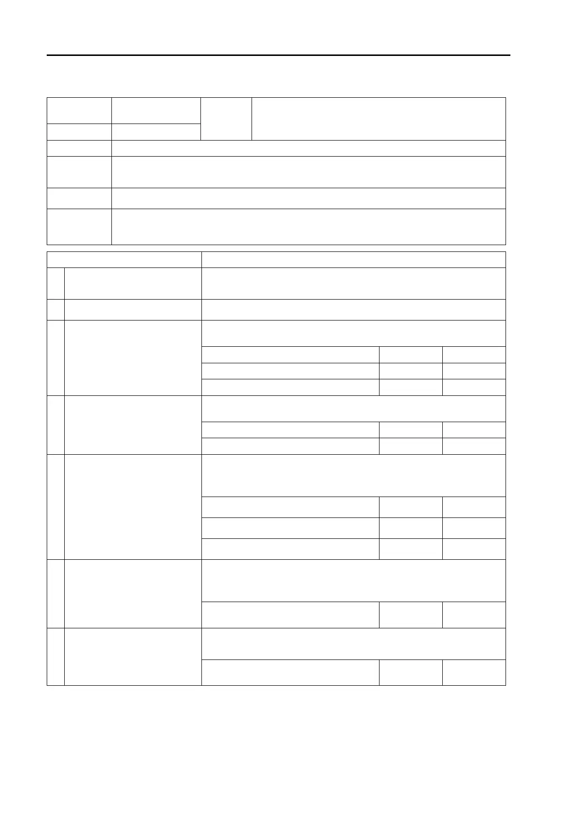
Failure code [CA132] Throttle Sensor Low Error
40-301 26 PC200, 200LC, 220, 220LC-8M0
SEN06133-00
Failure code [CA132] Throttle Sensor Low Error
Action
level
Failure code
Failure
Throttle Sensor Low Error
(Engine controller system)
L03 CA132
Detail of failure
q Low voltage appears in fuel control dial circuit.
Action of con-
troller
q Uses throttle value obtained before failure detection to run engine if failure is detected with starting
switch at ON position.
q Uses full throttle value to run engine if starting switch is set to ON position after failure detection.
Problem on
machine
q Engine speed cannot be controlled by using fuel control dial.
Related infor-
mation
q Signal voltage from fuel control dial can be checked with monitoring function.
(Code: 03000 Fuel control dial votage)
q Method of reproducing failure code: Turn starting switch to ON position.
Cause Procedure, measuring location, criteria and remarks
1
Defective wiring harness connec-
tor
See descriptions of wiring harness and connectors in "c: Electrical equip-
ment"of "Checks before troubleshooting" in "General information on trouble-
shooting", and check them.
2
Defective throttle sensor power
supply system
If failure code [CA2186] is also displayed, perform troubleshooting for it first.
3
Defective fuel control dial (throttle
sensor)
1. Turn starting switch to OFF position.
2. Disconnect connector P20 and connect T-adapters to male side.
Between P20 (male) (1) and (3) Resistance 4.0 to 6.0 kz
Between P20 (male) (2) and (3) Resistance 0.25 to 5.0 kz
Between P20 (male) (1) and (2) Resistance 0.25 to 5.0 kz
4
Open or short circuit in wiring har-
ness
1. Turn starting switch to OFF position.
2. Disconnect connector CE02, and connect T-adapters to female side.
Between CE02 (famale) (22) and (23) Resistance 4.0 to 6.0 kz
Between CE02 (famale) (9) and (23) Resistance 0.25 to 5.0 kz
5
Open circuit in wiring harness
(wire breakage or defective con-
tact of connector)
a If no failure is found in checks on cause 4, this check is not required.
1. Turn starting switch to OFF position.
2. Disconnect connectors CE02 and P20, and connect T-adapters to each
female side .
Between CE02 (female) (22) and P20
(female) (1)
Resistance Max. 1 z
Between CE02 (female) (9) and P20 (female)
(2)
Resistance Max. 1 z
Between CE02 (female) (23) and P20
(female) (3)
Resistance Max. 1 z
6 Short circuit in wiring harness
a If no failure is found in checks on cause 4, this check is not required.
1. Turn starting switch to OFF position.
2. Disconnect connectors CE02 and P20, and connect T-adapters to either
female side.
Between CE02 (female) (9) and (23), or
between P20 (female) (2) and (3)
Resistance Min. 1 Mz
7
Ground fault of wiring harness
(contact with ground circuit)
1. Turn starting switch to OFF position.
2. Disconnect connectors CE02 and P20, and connect T-adapters to either
female side.
Between CE02 (female) (9) or P20 (female)
(2) and ground
Resistance Min. 1 Mz