302 Troubleshooting by failure code, Part 2
Failure code [CA331] Inj #2(L#2) Open/Short Error
40-302 12 PC200, 200LC, 220, 220LC-8M0
SEN06134-00
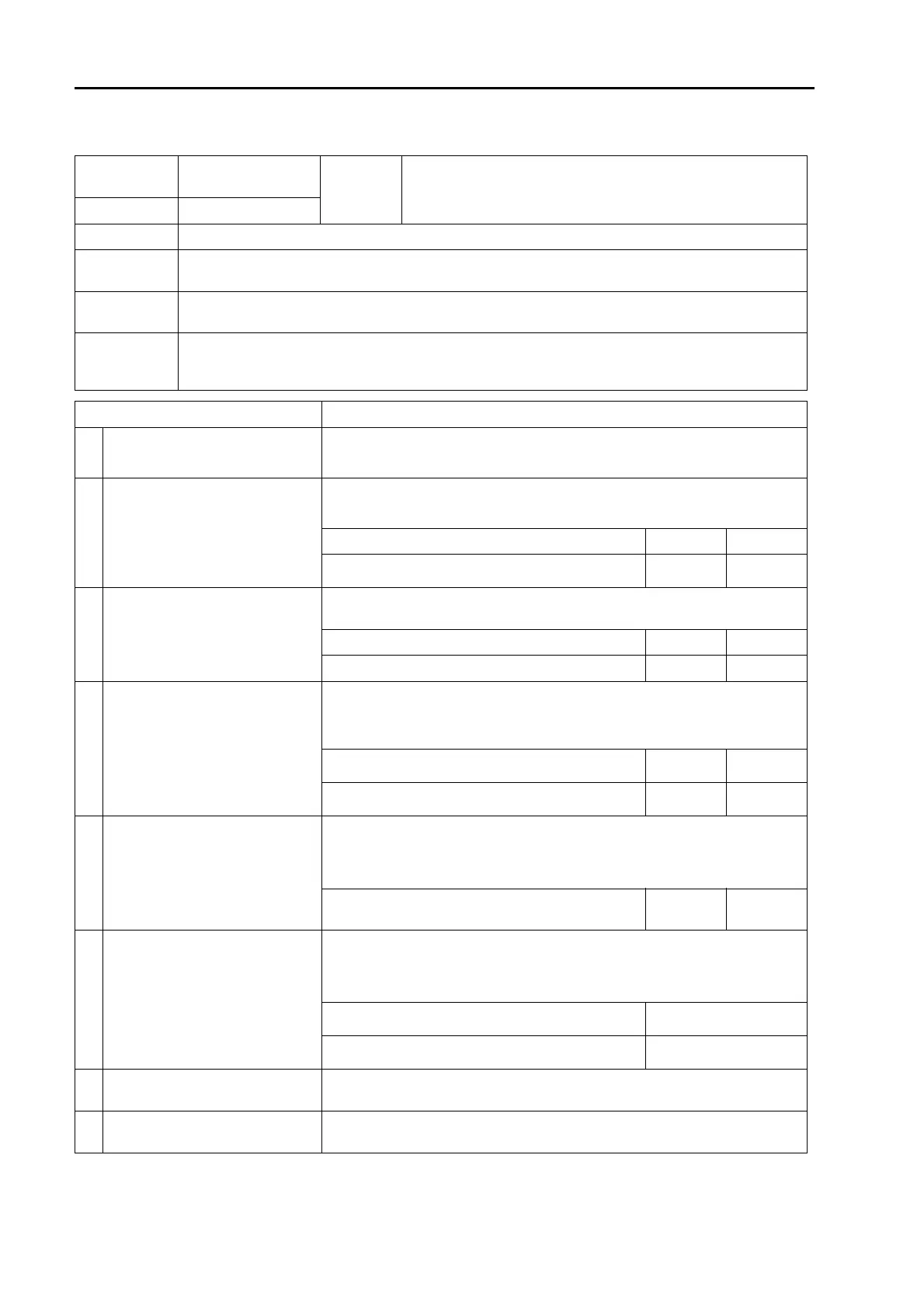
Failure code [CA331] Inj #2(L#2) Open/Short Error
Action
level
Failure code
Failure
Injector #2 (L#2) Open or Short Circuit Error
(Engine controller system)
L03 CA322
Detail of failure
q Open or short circuit is detected in drive circuit of No. 2 injector.
Action of con-
troller
q None in particular
Problem on
machine
q Poor combustions or hunting occurs.
q Engine output lowers.
Related infor-
mation
q Method of reproducing failure code: Start engine.
q While engine is running normally, approximately 65 V of pulse voltage is supplied to injector (+)
side. But it is pulse voltage and cannot be measured with multimeter.
Cause Procedure, measuring location, criteria and remarks
1
Defective wiring harness connec-
tor
See descriptions of wiring harness and connectors in "c: Electrical equipment"
in "Checks before troubleshooting" of "General information on troubleshoot-
ing", and check them.
2 Defective No. 2 injector
1. Turn starting switch to OFF position.
2. Disconnect connector INJECTOR CYL 1&2 and connect T-adapter to male
side.
Between INJECTOR CYL 1&2 (male) (A) and (B) Resistance Max. 2 z
Between INJECTOR CYL 1&2 (male) (B) and
ground
Resistance Min. 100 kz
3
Open circuit or ground fault in wir-
ing harness
1. Turn starting switch to OFF position.
2. Disconnect connector ECM and connect T-adapters to female side.
Between ECM (female) (54) and (51) Resistance Max. 2 z
Between ECM (female) (54) and ground Resistance Min. 100 kz
4
Open circuit in wiring harness
(wire breakage or defective con-
tact of connector)
a If no failure is found in checks on cause 3, this check is not required.
1. Turn starting switch to OFF position.
2. Disconnect connectors ECM and INJECTOR CYL 1&2 and connect
T-adapters to each female side.
Between ECM (female) (54) and INJECTOR CYL
1&2 (female) (B)
Resistance Max. 2 z
Between ECM (female) (51) and INJECTOR CYL
1&2 (female) (A)
Resistance Max. 2 z
5
Ground fault in wiring harness
(contact with ground circuit)
a If no failure is found in checks on cause 3, this check is not required.
1. Turn starting switch to OFF position.
2. Disconnect connectors ECM and INJECTOR CYL 1&2 and connect
T-adapters to either female side.
Between ECM (female) (54) or INJECTOR CYL
1&2 (female) (B) and ground
Resistance Min. 100 kz
6 Short circuit in wiring harness
1. Turn starting switch to OFF position.
2. Disconnect connectors ECM and INJECTOR CYL 1&2 and connect
T-adapter to female side of ECM.
a Check with multimeter in continuity mode.
Between ECM (female) (54) and each pin other
than (54)
No continuity (no sound
is heard.)
Between ECM (female) (51) and each pin other
than (51)
No continuity (no sound
is heard.)
7
Defective other cylinder injectors
or wiring harness
If different failure codes are displayed, perform troubleshootings for them on
ahead.
8 Defective engine controller
If no failure is found by above checks, engine controller is defective. (Since
this is an internal defect, troubleshooting cannot be performed.)

 Loading...