400 Troubleshooting of electrical system (E-mode)
E-24 Horn does not sound or does not stop
40-400 46 PC200, 200LC, 220, 220LC-8M0
SEN06138-00
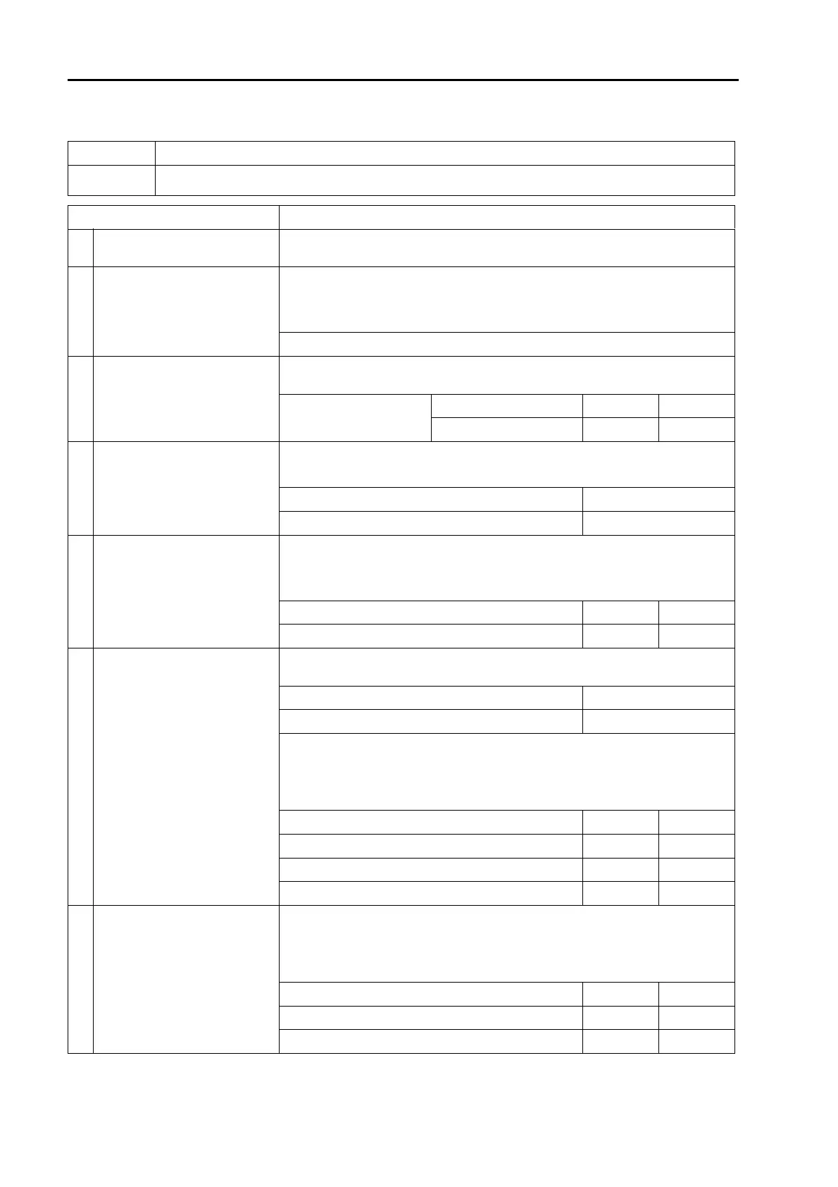
E-24 Horn does not sound or does not stop
Failure 1) Horn does not sound.
Related infor-
mation
Cause Procedure, measuring location, criteria and remarks
1 Defective fuse F01-5
If fuse F01(5) is broken, circuit probably has ground fault. In this case, perform
troubleshooting for cause 7 first.
2
Defective horn relay
(internal open or short circuit)
1. Turn starting switch to OFF position.
2. Replace horn relay (connector: R08) with another relay.
3. Turn starting switch to ON position.
4. Press L.H. knob switch.
If horn sounds, original horn relay is defective.
3
Defective horn switch
(internal open or short circuit)
1. Turn starting switch to OFF position.
2. Disconnect connector S10 and connect T-adapters to male side.
Between S10 (male) (1)
and (2)
Switch: OFF Resistance Min. 1 Mz
Switch: ON Resistance Max. 1 z
4
Defective high-tone horn (M07)
or low-tone horn (M08) (internal
open or short circuit)
1. Turn starting switch to OFF position.
2. Disconnect connectors M07 and M08, and connect T-adapters to each male
side.
Between M07 (male) (1) and (2) Continuity
Between M08 (male) (1) and (2) Continuity
5 Defective wiring harness
1. Turn starting switch to OFF position.
2. Disconnect connector R08 and connect T-adapters to female side.
3. Turn starting switch to ON position.
4. Press L.H. knob switch.
Between R08 (female) (1) and (2) Voltage 20 to 30 V
Between R08 (female) (3) and (2) Voltage 20 to 30 V
6
Open circuit in wiring harness
(Wire breakage or defective con-
tact)
1. Turn starting switch to OFF position.
2. Disconnect connector R08 and connect T-adapters to female side.
Between R08 (female) (5) and ground Continuity
Between R08 (female) (1) and ground Continuity
a If no failure is found by above checks, this check is not required.
1. Turn starting switch to OFF position.
2. Remove fuse F01-5.
3. Disconnect connectors R08 and S10, and connect T-adapters to each female
side.
Between F01-5 and S10 (female) (1) Resistance Max. 1 z
Between S10 (female) (2) and R08 (female) (1) Resistance Max. 1 z
Between R08 (female) (2) and ground Resistance Max. 1 z
Between R08 (female) (3) and F01(5) Resistance Max. 1 z
7
Ground fault in wiring harness
(contact with ground circuit)
a If fuse is not blown, this check is not required.
1. Turn starting switch to OFF position.
2. Remove fuse F01-5.
3. Disconnect connectors R08, M07, and M08, and connect T-adapters to
female side of R08.
Between R08 (female) (1) and ground Resistance Min. 1 Mz
Between R08 (female) (3) and ground Resistance Min. 1 Mz
Between R08 (female) (5) and ground Resistance Min. 1 Mz
 Loading...