This document is a Shop Manual for the Komatsu WA500-6 Wheel Loader, part of the GALEO series. It covers models with serial numbers 55001 and up, and is identified by Form No. SEN00236-05 and SEN00701-05. The manual provides comprehensive information for the maintenance, repair, and troubleshooting of the machine, organized into several key sections.
Function Description:
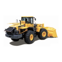
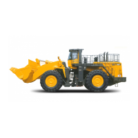
The Komatsu WA500-6 is a heavy-duty wheel loader designed for various applications, including construction, mining, and material handling. Its primary function is to scoop, lift, and transport bulk materials such as sand, gravel, dirt, and rock. The machine features a powerful engine, a robust power train, and an advanced hydraulic system to ensure efficient and reliable operation. Key operational systems include a sophisticated steering system for maneuverability, a comprehensive brake system for safety, and a work equipment system for precise material handling. The machine is equipped with an electrical system that controls various functions, including engine management, transmission, and operator interfaces. The inclusion of KOMTRAX terminal operations suggests advanced telematics capabilities for remote monitoring and management.
Important Technical Specifications:
The manual details the machine's specifications, including:
- Engine: SAA6D140E-5 (as referenced in the "Engine (SAA6D140E-5)" section under Disassembly and Assembly). This indicates a Komatsu-developed engine designed for high performance and efficiency, likely with emissions control features (implied by "ecot3" on the cover, which typically refers to Komatsu's Tier 3 compliant engines).
- Power Train: Includes a torque converter, transmission, transfer case, axles, differential (including limited slip differential), and final drives. The transmission control valve and ECMV (Electronic Control Modulation Valve) are critical components for smooth and efficient power transfer.
- Hydraulic System: Comprises a hydraulic tank, cooling fan motor and pump, steering pump, and work equipment hydraulic pump. The control valve, CLSS (Closed-center Load Sensing System), and PPC (Proportional Pressure Control) circuit accumulator are integral for precise and responsive control of the work equipment.
- Brake System: Features a brake valve, slack adjuster, accumulator charge valve, PPC relief valve, and accumulators for both service and parking brakes.
- Steering System: Includes a steering column, steering control valve, steering valve, stop valve, joystick steering lever linkage (if equipped), steering cylinder, and a diverter valve, with provisions for an emergency steering piping diagram.
- Electrical System: Divided into multiple parts covering machine monitor, work equipment control system, transmission controller system, electric transmission control, engine starting/stopping/preheating circuits, parking brake circuit, backup/stop/small/head/working lamp circuits, horn circuit, wiper/window washer circuits, and various sensors. KOMTRAX terminal system is also a significant electrical component.
- Cab and Attachments: ROPS (Roll-Over Protective Structure) cab for operator safety, and an air conditioner for comfort.
- Weight Table: Provides detailed weight information for various components and the overall machine.
- Fuel, Coolant, and Lubricants Table: Specifies the types and quantities of fluids required for proper operation and maintenance.
Usage Features:
The WA500-6 is designed for ease of operation and maintenance.
- Control Systems: The machine utilizes advanced control systems such as the ECMV for transmission and CLSS for hydraulics, which contribute to smooth and precise operation. The option for joystick steering lever linkage enhances operator comfort and control.
- Operator Interface: The machine monitor system provides critical operational data and diagnostic information to the operator. Indicator lamps for the KOMTRAX terminal and proximity switch operation indication lamp aid in monitoring machine status.
- Safety Features: A robust brake system, including parking brake control and an emergency parking brake release valve, ensures operational safety. The ROPS cab provides protection for the operator.
- Work Equipment: The work equipment linkage, bucket, bucket positioner, and boom kick-out features allow for efficient and precise material handling. The work equipment electric lever provides ergonomic control.
- Diagnostic Capabilities: The manual extensively covers troubleshooting by failure code (Display of code) for various systems (engine, electrical, hydraulic, mechanical), indicating built-in diagnostic features to assist in identifying and resolving issues. Special functions of the machine monitor (EMMS) further enhance diagnostic and adjustment capabilities.
Maintenance Features:
The Shop Manual is a critical resource for maintaining the WA500-6.
- Detailed Procedures: It provides detailed instructions for testing and adjusting various components, including engine speed, exhaust gas color/temperature, valve clearance, compression pressure, blow-by pressure, engine oil pressure, intake air (boost) pressure, fuel system (pressure, return rate, leakage, bleeding air), transmission speed sensor, power train oil pressure, steering stop valve, steering oil pressure, hydraulic drive fan, brake pedal, brake performance, accumulator charge pressure, wheel brake oil pressure, parking brake performance, and work equipment control lever/PPC oil pressure.
- Troubleshooting Guides: Extensive sections are dedicated to troubleshooting by failure code, covering electrical, hydraulic, mechanical, and engine systems. This allows technicians to diagnose problems efficiently using error codes displayed by the machine.
- Disassembly and Assembly: Comprehensive guides for disassembling and assembling major components like the engine, cooling system, power train, brake system, undercarriage, frame, hydraulic system, work equipment, cab, and electrical system. This ensures proper procedures are followed during repairs.
- Standard Value Tables: Provides standard service values for the engine and chassis, which are essential for verifying component performance and ensuring proper adjustments.
- Diagrams and Drawings: Includes hydraulic and electrical diagrams and drawings, which are crucial for understanding system layouts, tracing circuits, and performing accurate diagnostics and repairs.
- Special Tools and Methods: Mentions "Tools for testing, adjusting, and troubleshooting," indicating the need for specific tools. It also outlines methods for releasing residual pressure in fuel, brake accumulator, and work equipment circuits, and procedures for flushing the torque converter and transmission hydraulic circuit.
- Preventive Maintenance: The "Structure, function and maintenance standard" sections provide insights into how components work, which is foundational for understanding maintenance requirements and preventing failures.
- Component-Specific Maintenance: Detailed sections on individual components like the torque converter regulator valve, transmission control valve, main relief valve, torque converter relief valve, and lubrication relief valve, provide specific maintenance and adjustment information.
- Handling Guidelines: Includes sections on "Handling of electric equipment and hydraulic component," "Handling of connectors newly used for engines," "How to read electric wire code," and "Precautions when carrying out operation," emphasizing best practices for safe and effective maintenance.
- Tightening Torque: A "Standard tightening torque table" ensures that fasteners are tightened correctly to prevent loosening or damage.
- Conversion Table: Provided for converting units of measurement, useful for international technicians or when working with different measurement systems.