UAB KOMFOVENT we reserve the right to make changes without prior notice.
MOU2-20-03
5
Fig. 2.1
Fig. 2.2
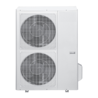
2. OUTDOOR UNIT INSTALLATION
2.1. Outdoor Unit Installation Instructions
Step 1: Select installation location.
The outdoor unit should be installed in the location that meets the following requirements:
• Place the outdoor unit as close to the indoor unit as possible.
• Ensure that there is enough room for installation and maintenance.
• The air inlet and outlet must not be obstructed or exposed to strong wind.
• Ensure the location of the unit will not be subject to snowdrifts, accumulation of leaves or other seasonal
debris. If possible, provide an awning for the unit. Ensure the awning does not obstruct airflow.
• The installation area must be dry and well ventilated.
• There must be enough room to install the connecting pipes and cables and to access them for maintenance.
• The area must be free of combustible gases and chemicals.
• The pipe length between the outdoor and indoor unit may not exceed the maximum allowable pipe length.
• If possible, DO NOT install the unit where it is exposed to direct sunlight.
• If possible, make sure the unit is located far away from your neighbors’ property so that the noise from the
unit will not disturb them.
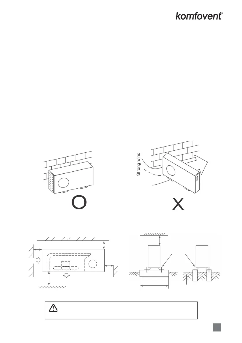
• If the location is exposed to strong winds (for example: near a seaside), the unit must be placed against the
wall to shelter it from the wind. If necessary, use an awning. (See Fig. 2.1 & 2.2)
• Install the indoor and outdoor units, cables and wires at least 1 meter from televisions or radios to prevent
static or image distortion. Depending on the radio waves, a 1 meter distance may not be enough to eliminate
all interference.
Step 2: Install outdoor unit.
Fix the outdoor unit with anchor bolts (M10)
5
Outdoor Units
Outdoor unit installation
Cautions
.HHSWKLVXQLWDZD\IURPGLUHFWUDGLDWLRQRIWKHVXQRURWKHUKHDWHUV
,IXQDYRLGDEOHSOHDVHFRYHULWZLWKDVKHOWHU
,QSODFHVQHDUFRDVWRUZLWKDKLJKDWWLWXGHZKHUHWKHZLQGLVYLROHQWSOHDVHLQVWDOOWKHRXW-
GRRUXQLWDJDLQVWWKHZDOOWRHQVXUHQRUPDOSHUIRUPDQFH
8VHDEDIÀHZKHQQHFHVVDU\
,QWKHFDVHRIH[WUHPHO\VWURQJZLQGSOHDVHSUHYHQWWKHDLUIURPÀRZLQJEDFNZDUGVLQWRWKH
outdoor unit. ( Refer to chart 16)
Locate the outdoor unit as close to the indoor unit as possible.
7KHPLQLPXPGLVWDQFHEHWZHHQWKHRXWGRRUXQLWDQGREVWDFOHVGHVFULEHGLQWKHLQVWDOODWLRQ
chart does not mean that the same is applicable to the situation of an airtight. Leave open
WZRRIWKUHHGLUHFWLRQV$%&
Necessary room for installation and maintenance
5HIHUWRFKDUWFKDUW
,ISRVVLEOHSOHDVHUHPRYHWKHREVWDFOHVQHDUE\WRSUHYHQWWKHSHUIRUPDQFHIURPEHLQJLPSHGHGE\WRROLWWOH
of air circulation.
7KHPLQLPXPGLVWDQFHEHWZHHQWKHRXWGRRU XQLW DQGREVWDFOHVGHVFULEHGLQWKH LQVWDOODWLRQ FKDUWGRHVQRW
PHDQ WKDW WKH VDPH LV DSSOLFDEOH WR WKH VLWXDWLRQ RI DQ DLUWLJKW URRP /HDYH RSHQ WZR RI WKH WKUHH GLUHFWLRQV
$%&
Chart 1
6WURQJZLQG
Wall or obstacle
Air inlet
Air inlet
>30 cm
>60 cm
C
Air outlet
>200 cm
A
>30 cm
Maintain channel
>60 cm
1HFHVVDU\ZLGWK
)L[ZLWKEROW
Deep foundation
Fig. 2.3
• Be sure to remove any obstacles that may block air circulation.
• Make sure you refer to Length Specications to ensure there is
enough room for installation and maintenance.
 Loading...