UAB KOMFOVENT we reserve the right to make changes without prior notice.
MOU2-20-03
7
Model
Outdoor unit dimensions
W × D × H
Mounting Dimensions, mm
Distance A Distance A
MOU-12HFN8 800x333x554 514 340
MOU-18HFN8 800x333x554 514 340
MOU-24HFN8 845x363x702 540 350
MOU-36HFN8 946x410x810 673 403
MOU-48HFN8 952x410x1333 634 403
MOU-55HFN8 952x410x1333 634 404
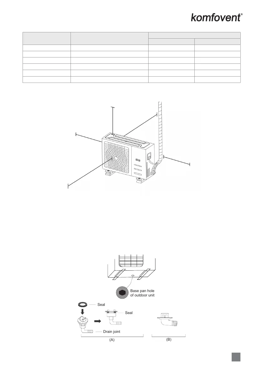
NOTE: The minimum distance between the outdoor unit and walls described in the installation guide does not
apply to airtight rooms. Be sure to keep the unit unobstructed in at least two of the three directions (M, N, P)
(See Fig. 2.7).
200 cm / 78” in front
30 cm / 11.8” on left
60 cm / 23.6” above
30 cm / 11.8” from back wall
60 cm / 23.6” on right
M
N
P
Fig. 2.7
Drain Joint Installation
Before bolting the outdoor unit in place, you must install the drain joint at the bottom of the unit (See Fig. 2.8).
1. Fit the rubber seal on the end of the drain joint that will connect to the outdoor unit.
2. Insert the drain joint into the hole in the base pan of the unit.
3. Rotate the drain joint 90° until it clicks in place facing the front of the unit.
4. Connect a drain hose extension (not included) to the drain joint to redirect water from the unit during heating
mode.
NOTE: Make sure the water drains to a safe location where it will not cause water damage or a slipping hazard.
Base pan hole
of outdoor unit
Seal
Seal
Drain joint
(A)
(B)
Fig. 2.8
 Loading...