Do you have a question about the Komshine KFI-40 and is the answer not in the manual?
Components for securing and guiding the optical fiber during testing, including cover, plunger, groove, and lock.
Internal optical parts, battery access, and the dust cover housing the VFL and LED interface.
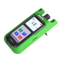
LCD display for power/frequency and direction indicators for signal location.
Controls for power on/off, backlight activation, and VFL function.
Steps and indicators for identifying optical fiber signals, including direction and frequency detection.
Instructions for activating and using the Visual Fault Locator (VFL) function.
Guide on how to turn the built-in LED flashlight on and off for illumination.
Overview of the fiber identifier's role in maintenance and its core capabilities.
Highlights of the device including fixture design, display, signal recognition, and integrated VFL/LED.
Key parameters like wavelength range, signal types, power, and VFL capabilities.
Recommended altitude limits and crucial safety precautions for handling and use.
List of items included in the product packaging.
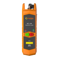
The KFI-40 Fiber Identifier is a versatile and essential tool for fiber optic network maintenance, designed for non-destructive fiber identification. It integrates multiple functionalities, including fiber identification, a Visual Fault Locator (VFL), and LED lighting, making it suitable for a wide range of field applications.
The primary function of the KFI-40 is to identify optical fibers without interrupting service. This is crucial during maintenance, installation, wiring, and recovery processes where continuous operation is required. To achieve this, a modulated signal (270Hz, 1KHz, or 2KHz) at 1310nm or 1550nm is injected into one end of the optical fiber. The KFI-40 then detects this signal on the line, indicating the presence of a signal and its direction.
The device features an LCD display that shows the power value and frequency of the detected signal. If a signal is present, left and right direction lights illuminate to indicate the signal flow. If no signal is detected, the LCD displays "LO," and the direction indicator lights may flicker. The device also provides an audible buzzing sound when a signal frequency (2KHz, 1KHz, 270Hz) is correctly identified, although this sound may not occur if the signal is too weak. It's important to note that the KFI-40 does not specify power accuracy and should not be used to determine the actual signal strength in the fiber.
In addition to fiber identification, the KFI-40 incorporates a Visual Fault Locator (VFL) function. This VFL uses a 2.5mm universal interface and provides an output power of up to 1mW. It can detect fiber breaks or sharp bends within a range of 3-5km. The VFL supports both continuous wave (CW) and pulsed output modes. To use the VFL, the user turns on the power, opens the dust cover, inserts the fiber into the laser connector, and presses the VFL button. A short press toggles between CW, pulsed output, and off.
The device also includes an integrated LED lighting function, which is useful for working in dark environments. To activate the flashlight, the user turns on the power, opens the dust cover, and presses the "--" button. A short press of the "--" button turns the flashlight off.
The KFI-40 Fiber Identifier is a robust and user-friendly device that streamlines fiber optic network maintenance by providing reliable identification, fault location, and convenient illumination in a single, portable unit.
| Brand | Komshine |
|---|---|
| Model | KFI-40 |
| Category | Measuring Instruments |
| Language | English |