3.3 Terminal connections
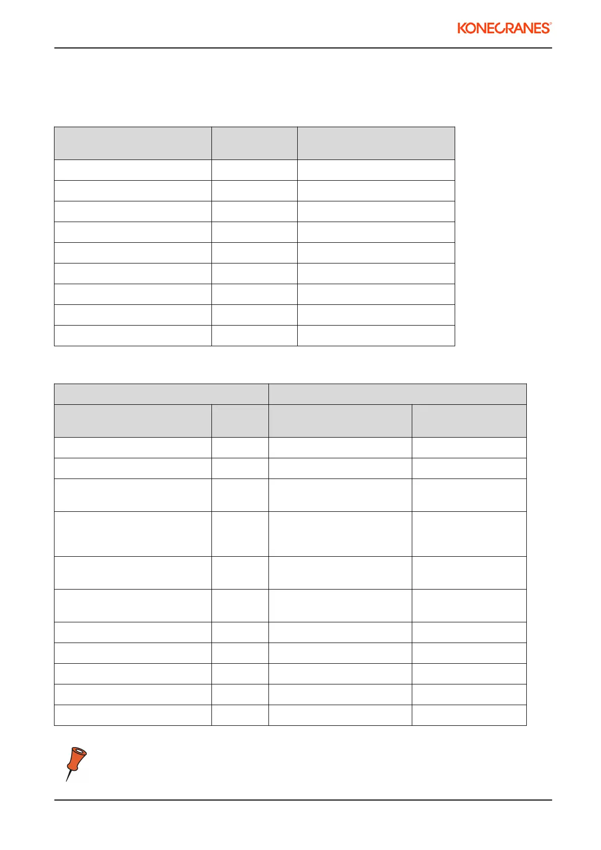
Table 1. Power terminals
Description of Terminal DynADrive 022
Terminal X2
DynA45 006 Power terminals
Power supply, phase 1 L1 L1
Power supply, phase 2 L2 L2/N
Power supply, phase 3 L3 L3
Motor supply, phase 1 U U/T1
Motor supply, phase 2 V V/T2
Motor supply, phase 3 W W/T3
Braking resistor, positive R+ R+
Braking resistor, negative R- R-
Protective earth PE PE
Table 2. Control terminals
DynADrive 022 DynA45 006
Description of Terminal Terminal
X1
Description Control board
terminals
Drive command, direction 1 1 Drive command, direction 1 1
Drive command, direction 2 2 Drive command, direction 2 2
Speed 2 / Acceleration command 3 Speed 2 / Acceleration
command
3
Slowdown/Stop limit, direction 1 4 Common slowdown,
Slowdown/Stop limit, direction
1
4
Slowdown/Stop limit, direction 2 5 Common stop, Slowdown/
Stop limit, direction 2
5
Common DI1-5 6 Motor temperature
protection / External stop
6
Normally open relay contact 7 Common DI1-6 7
Normally open relay contact 8 Normally open relay contact 8
Empty 9 Normally open relay contact 9
Motor thermistor, T1 10
Motor Thermistor, T2 11
Terminal X1 and control board terminal pins may have different functions!
020145en / Revision D / 2015-04-29
7/31
This document and the information contained herein, is the exclusive property of Konecranes Plc. and represents a non-public, confidential and proprietary trade secret that may not be
reproduced, disclosed to other parties, altered or otherwise employed in any manner whatsoever without the express written consent of Konecranes Plc.
Copyright
©
(2014) Konecranes Plc. All rights reserved.