Do you have a question about the Konica Minolta FS-533 and is the answer not in the manual?
Warning regarding suffocation risk from plastic bag; keep away from children.
Notes on illustration differences and discarding removed parts.
Turn off power, unplug, remove protective tape, materials, and accessories.
Instruction to remove a specific screw and its washer from the unit.
Check output tray for snap-fit hook; follow conditional steps based on model.
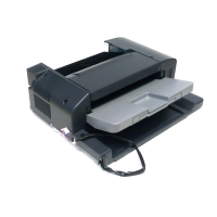
Steps to remove the main unit's front cover, rear left cover, and a knockout.
Careful insertion into the main unit, adjusting position, and securing.
Adjust brush position and install the supplied rail cover onto the finisher.
Reinstall covers, connect finisher cables, and secure with cable tie.
| Brand | Konica Minolta |
|---|---|
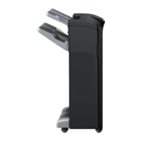
| Model | FS-533 |
| Category | Finishers |
| Language | English |